Your online Softimage Educational Resource

The blog has been online for more than 4 years and there’s still not a single post even remotely related to the delicious brew called coffee… Perhaps it will someday, but in the meantime you can read the articles about Softimage. Most of the material are tutorials and Q&As I’ve written for 3D World Magazine sometime between today and 2003. If you have any questions please don’t hesitate sending me an email.


Thanks to Letterbox Animation Studios for hosting all the scene files.

Make sure you visit their Redi-Vivus.com for 100s of hours of free XSI video tutorials.

Wednesday, May 20, 2009

Adding Ambient Occlusing as a lens effect

Adding AO globally
While you commonly would setup and render the ambient occlusion in a separate pass, it doesn’t mean it can’t be done in a single pass as well. By adding the AO to the camera rather than the individual materials, you can control the effect globally and you don’t have to change a single material. Open the scene cube.scn from this issues DVD. Press [8] to open an Explorer, select the Camera and press [7] to open a Render Tree.

Using a lens shader
Connecting the AO directly to the camera wouldn’t make much sense at all, but you’ll need a few other nodes as well to make it work. First you’ll need a lens shader. You’re not going to use any of its features, so any lens shader will do. From the Nodes > Illumination menu choose More. Go to the DSPresets\Shaders\Lens folder, select the Lens Effect and click Ok. Open the Lens Effect PPG and change the Mode to Bypass Effects.
The ambient occlusion
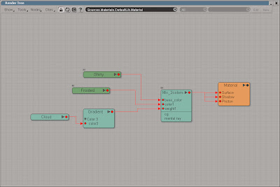
Add a Mix 2 Colors node (from the Nodes > Mixers menu) and an Ambient Occlusion (from the Nodes > Illumination menu). Connect the Lens_Effect to the base_color input on the Mix2color node and the AO node to the color1. Then connect Mix2color node to the Lens Shader input on the Camera node. Open the Mix2color PPG, set the Weight to pure white, R:1, G:1, B:1 and change the Mode to Hide/Reveal(Multiply).

The project files used in this tutorial can be found at: http://dl.dropbox.com/u/3834689/CaffeineAbuse/AmbientOcclusion.zip


Read the full post>>

Friday, May 15, 2009

Animating frost growing across the surface


Animating a gradient sweeping across the surface is a very quick and efficient way to create a transition from one material to another.

This is a very common question. Okay perhaps not the frosted effect, but the part about changing the textures or materials for an object over time. You obviously need a surface for the material so start a new scene and create a simple object. Or just open the scene frost.scn from this issues DVD. Select the frost object and from the Get > Material menu choose Phong and Press [7] to open a Render Tree. Get a Gradient node from the Nodes > Texture menu and a Mix 2 Colors node from the Nodes > Mixers menu. Connect the gradient node to the Weight input of the Mix_2colors node and the Mix_2colors node to the surface input of the Material node. Double click on the gradient node to open the PPG and switch to the Texture tab. Click the New button and from the menu choose Planar XY. Switch back to the RGBA Gradient tab and click the White/Black button in the Preset section to set the gradient to white and black. While this will create a nice gradual transition, it’s to uniform and unexciting. To break up the gradient you’ll need to add a new marker. Click somewhere in the middle of the gradient slider to add a third marker. With the new marker selected, click on the connection icon for the color and from the menu choose Cloud. Switch to the Texture tab, click the New button and choose Spatial. Switch back to the Cloud tab. Set the Clouds color to a light gray, such as R: 0.8, G: 0.8, B0.8 and the Sky to a slightly darker gray, R: 0.58, G: 0.58, B0.58. Switch to the Advanced tab and change the X,Y and Z maximum to 10.

From the Nodes > Illumination menu, add two Pong shaders and connect one to the base_color input of the Mix_2colors node and the other to the color1 input. Modify the Phong shaders to your liking and close the Render Tree. In a viewport, select the planar Texture_Support and scale it to about 0.4 on the Y-axis. Position it just below the frost object and press [K] to set a keyframe. Go to frame 50 and move the Texture_Support so it’s just above the object and set a new keyframe. Render the animation and you’re done.
Once the gradient is in place, you can replace the solid colors with textures to create complicated pattern.

The project files used in this tutorial can be found at: http://www.redi-vivus.com/Caffeineabuse/Frost.zip

Quick tip
You can create a completely different look for the transition just by replacing the cloud texture with any of the other textures nodes.


Read the full post>>

Thursday, May 14, 2009

Rendering XXL Sized images

While images for prominent 3d magazines may require a resolution of 300dpi, posters and billboards requires far less.
While the images for a typical brochure often are printed at a resolution of between 150 and 300 dots per inch (dpi) posters rarely exceeds 100dpi. Once you reach the size of billboards you’ll probably end up at a resolution less than 30dpi. With the above in mind you should have limit the need for extreme high resolution rendering, but there are situations when you do want the extra pixels. The central problem with large images is the amount of RAM needed. Not only do you need to cover the frame buffer/image itself which can easily grow to several hundred mega bytes (this is without considering the recourses need to actual compute the rendering) you also need to have this amount of free continuous memory.

The idea is to split the rendered image into smaller images and then stitch them back together in Photoshop or XSI Illusion (FX Tree) for that matter. This is done by changing the focal length of the camera and then shifting its optical center to the left, right, up and down. This won’t change the perspective in the image, just just which part and how much you see of it. To maintain the overall control of your shots, you’ll use one camera for the staging and four additional cameras for the render. Any changes made to the main camera will then automatically get propagated to the extra cameras by the use of expression, but with the added offset.

Open the scene SuperSize.scn from this issues CD. Press [8] to open an Explorer, expand the Cam_UpperLeft_Root node and click on the icon next to the Cam_UpperLeft to open its PPG. Switch to the Projection Plane tab and check the Enable checkbox. Right click on the animation icon (green dot) next to the Focal Length and choose Expression Editor. Enter Main_Camera.camera.projplanedist * 2 and click the Apply button. This will link the Focal Length to the main camera and double it (since you are to split the size of the rendered images in half). Open the Expression Editor for the Optical Center Shift X axis and enter Main_Camera.camera.projplanewidth * -0.5 This will offset the optical center by half the main cameras film aperture. Enter the expression Main_Camera.camera.projplaneheight * 0.5 for the Y Axis. Repeat the same procedure for the other three cameras. For the Cam_UpperRight use Main_Camera.camera.projplanewidth * 0.5 for the X shift, Cam_LowerLeft should use * -0.5 for both the X and Y shift (projplanewith and projplaneheight) and the Cam_LowerRight should use *-0.5 for the Y shift.

By using expressions the properties, and their added offset, is automatically propagated from the main camera to the extra cameras.

The project files used in this tutorial can be found at: http://www.redi-vivus.com/Caffeineabuse/XXL_Rendering.zip


In case the redi-vivus.com link doesn’t work, you can find a copy of the project files here: https://www.dropbox.com/s/qj37guhrl5k7qr3/XXL_Rendering.zip


Quick tipThe very same approach can successfully be used to create screen captures that is larger than your display resolution as well.


Read the full post>>

Coloring hair using procedural textures

Step 01
Creating the procedural
Select the pelt object and press [7] to open a Render Tree. Get a Fractal node (from the Nodes > Texture) and a Color Matte node (from the Nodes > Color Channels). Connect the Fractal node to the Input of the Color Matte node and the Color Matte node to the Ambient and Diffuse input of the Blinn node. Open the Fractal PPG. In the Texture tab, click the New button and choose Planar XZ. Switch to the Advanced tab and set the UV Remap Maximum to 5 for all three axis.


Step 02
Creating the texture


Open the Color Matte PPG. In the Component tab, change the Channel to Average RGB. Switch to the Component Range tab and check the Range Enabled checkbox. Set the Minimum delta to 0 (zero), the Minimum threshold to about 0.45 and the Maximum delta to 1. Change the Inside Value to a light brownish color and the Outside Value to a dark brown. Select the Color_Matte node and press [Ctrl] + [C] to copy the branch. Press [Ctrl] + [2] to switch to the Hair toolbar. Select all the polygons on the topside of the pelt and from the Hair > Create menu choose From Selection


Step 03
Transfer UV’s to the Hair
Select the Hair and from the Modify menu choose Transfer Map. Press [8] to open an Explorer. Expand the Pelt > Polygon Mesh > Cluster > Texture_Coordinates node and pick the Texture_Projection (Planar XZ). This will copy the UV information from the mesh to the hair operator. With the hair selected, press [7] to open a Render Tree and press [Ctrl] + [V] to paste the nodes from the Pelt material. Connect the Color_Matte to the DiffuseRoot input of the Hair_Render node.

The project files used in this tutorial can be found at: http://www.redi-vivus.com/Caffeineabuse/HairProceduralColor.zip


Read the full post>>

Animating a mechanic billboard in Softimage XSI

While the mechanical billboard is outdated at best, your virtual version is just about to start its glory days.

Start by opening the Billboard.scn scene from this issues CD. The scene contains a bunch of trilons or triangular prisms, 300 to be precise. Using a couple of thousands would obviously be more striking but for the sake of demonstration the number is keep low. While any of the prisms could be used to animate their rotation, it’s a good idea to separate the animation parameters from the actual billboard. Start by selecting the null object named Prisms_Rotation. Press [C] to activate the rotation tool and press [K] to set a keyframe at frame 1. Go to frame 16, rotate the Prisms_Rotation 120 degrees on the Y-axis and set a new keyframe. With the rotation still at 120, set another keyframe at frame 80. Press [0] (zero) to open the Animation Editor and select the function curve for the Y rotation (roty). From the Curves menu choose relative Cycle. To change the pace of your mechanic billboard, just move one of the 3 keyframes.

Press [2] to switch to the Animate toolbar. From the Create > Parameter menu choose New Custom Parameter Set. Enter Billboard as the name and click OK. Press [8] to open an Explorer, select the Billboard parameter set and press [Shift] + [P] to add a new custom parameter. Name the new Parameter Rotation_Delay. The parameter will be used to control the offset of the prisms. Changing the slider will automatically change the delay. The offset is evaluated in seconds; consequently you’re going to use very small values. Change the Maximum Value Range to 0.01 and click OK to close the PPG.

Open an Explorer and select the Prism_No1. Scroll down to Prism_No300 and shift select it to select all the objects in order from 1 to 300. Press [Alt] + [4] to open the Script Editor. Set your script language to Jscript (File > Preferences) and enter the text beneath.
Press the Run button in Script Editor to execute the script. Open the Bilboard PPG and playback the animation while changing the Time_Delay slider.

Using a simple loop in Jscript adds the expression with the delayed rotation in seconds rather than the frustrating hour required if done manually.

The project files used in this tutorial can be found at: http://www.redi-vivus.com/Caffeineabuse/Billboard.zip

Quick tip
The order in which the objects are selected also controls the extent of the offset, which in turn is set by Rotation_Delay slider. So, select the object in the order you want them to turn.


Read the full post>>

Create procedural leather material in XSI

Step 01
Color variation
Start by installing the BA Shader Collection Essential add-on from http://www.binaryalchemy.de/index_dev.htm. Open the scene leather.scn from this issues CD. Press [8] to open an Explorer and select the group Leather_material. From the Get > Material menu choose Blinn and press [7] to open a Render Tree. From the Nodes > Textures menu choose More… In the Browser, click the Paths button and choose the Binary Alchemy Shader Collection – Essential. Select the BA_fractal4d and press OK.


Step 02
Creating bumpmap
Double-click on the BA_fractal4d node to open its PPG. Change the settings according to the above screenshot and then connect the node to the diffuse input of the Blinn node. Get a second BA_Fractal4d node and a BA_cell3d texture by repeating the previous step. Open the PPG for the BA_fractal node, switch to the Noise tab and set the Noise Type to Fractalsum. In the Bump tab, check the Enable Bump and Bumpmap only checkboxes and set the Bump Factor to 1. Switch to the Texture Support and set the Coordinate Scale to 8 on all three axis.
Step 03
Creating bumpmap variation
Open the BA_cell3d PPG and switch to the Cell tab and change the Cell Shape to Random (less black holes) and increase the Power Level to 3. In the Bump tab check the Enable Bump and Bumpmap only checkboxes and set the Bump Factor to -250. Switch to the Texture Support tab and change the coordinate Pre-Scale to Small Noise and the Scale on all three axis to 4. From the Nodes > Mixers menu get a Mix 2 Colors node. Connect the BA_cell node to the base_color input of the Mix_2colors node and the BA_fractal to the color1 input. Then connect the Mix_2colors node to the Bump Map input of the Material node.

The project files used in this tutorial can be found at: http://www.redi-vivus.com/Caffeineabuse/ProceduralLeather.zip


Read the full post>>

Tuesday, May 5, 2009

Simulating an effervescent tablet using particles

Step 01
Creating particles
The first think you’ll need is obviously a glass of water and a tablet, so start by opening the scene effervescent_tablet.scn from this issues CD. Press [4] to switch to the Simulate toolbar. Select the tablet and from the Create > Particles menu choose From Selection. In the particle PPG, change the settings as shown in the above screenshot (a high-resolution version can be found on the CD).

Step 02
Adding bubbles
In the Particle_Billboard section, switch to the Make Connection tab and click the Sprite button. Switch to the Sprite tab (in the PType section) and click the New button > New From File... and pick the SpriteBubble.pic image from the CD. From the Get > Force menu, choose Gravity. Change the Amplitude to about 10. Rotate the gravity -180 degrees along the X-axis so it points upwards.

Step 03
Creating the environment
Select the cloud and from the Modify > Environment menu, choose Apply Force and pick the gravity object. With the cloud still selected, click Modify > Environment Modify > Environment > set Obstacle and pick the glass. In the obstacle PPG, change the Obstacle type to Actual Shape. Set a new obstacle but this time, pick the WaterSurface. From the Inspect > Events menu choose PEvent1 and, in the PPG, change the Action to Disappear.

The project files used in this tutorial can be found at: http://www.redi-vivus.com/Caffeineabuse/Effervescent_Tablet.zip


Read the full post>>