 While having the largest box of crayons in class may have been thrilling when you were a kid, ithad little or nothing to do with the quality of the images you drew. Although we doubt thatanyone would seriously argue with this, it’s something people often forget when it comes to 3D. With the manuals of modern 3D applications weighing more than the contents of a schoolsatchel, it’s as easy to be dazzled by the number of features available as it was by the number of crayons. But the basics of 3D are exactly that – basic enough for anyone to follow.
During this four-part tutorial series, we’ll introduce you to the fundamental concepts of 3D animation. While primarily aimed at newcomers, we also encourage more experienced users to drop by our 3D kindergarten; no matter how well you know your software, there’s no substitute to an understanding of the principles of weight and timing. At the end of the day, animation is all aboutbringing things to life, not marvelling at the tools employed to do so.
There are few exercises that can be used to explain the basic principles of animation as effi ciently as recreating the motion of a bouncing ball. The staple of many college courses, this simplelooking task actually involves all the elements that will make or break a much more complex animation. To add a new twist to the proceedings, we’ve replaced the ball with the ‘70s-style toy above. In the first of these tutorials, we’ll simply concentrate on making it bounce in a realistic manner. In future issues, we’ll tackle the slightly more complex challenge of injecting emotion into its movements.
For this tutorial, we’ll be using SoftimageXSI – we’ve included a copy of the educational version (the SoftimageXSI Mod Tool) on the CD. Although it has certain limitations, it will be more than adequate for the purpose. We’ve also provided a model of the toy itself on the disc, pre-built and ready to animate. Just load it in, and follow the walkthrough to the right. If you get stuck with any of the technical terms, you can download a glossary from http://www.3dworldmag.com/
All the project files and the original tutorial as it appeared in 3D World can be found at http://www.computerarts.co.uk/tutorials/3d__and__animation/get_started_in_animation_part_1
STAGE ONE The basics of bounce

Step 1
Let’s start off by having a closer look at what’s happening to the hopper in reality, and what we’re expecting to recreate in our animation. The image
above shows the three extremes position of a ball going down and back up. While this theoretically would be enough information to produce an animation, it doesn’t tell us anything about what’s happening between those positions.
 Step 2
On this image we’ve added the path of which the ball would travel along. Note that nearly every natural movement found in real life can be traced in ark-like paths rather than straight lines between point a and point b. So regardless of the subject this is important to remember, as animating motions, rotations, etc in straight lines will come of jerky and appear unnatural. Now, let’s add the timing.
 Step 3
As the ball falls towards the ground, it accelerates due to the force of gravity. Since the ball is traveling faster at each frame it will obviously travel a grater distance, creating larger spacing between each keyframe till it makes contact with the ground. Directly after contact, we get the opposite action. The ball’s momentum pushes it of the ground rapidly, but slows down as gravity catches on.
Stage two Setting keyframes
 Step 4
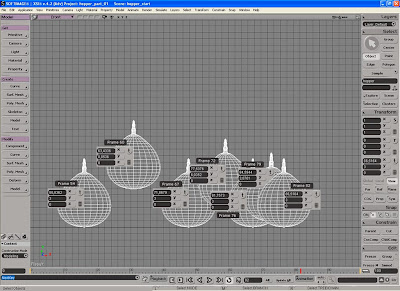
With the basic concept clear enough, we should be able to put it into practice. Locate the file hopper.scn from the cover CD and open it. The scene it’s pretty much a 3D representation of the image from the previous step, containing two objects; the hopper, which is our stand-in for the ball and a grid, which will act as the ground.
 Step 5
The first thing we’ll do is creating a sort of rough breakdown of the animation, just establish the key positions or the extremes and build upon these. While you usually work on several parameters simultaneous, for clarity we’ll focus on one at the time. Click on the large arrow in the top right corner (hotkey spacebar) to ensure you have the selection tool enabled, and select the Hopper object.
 Step 6
Next, maximize the front viewport by position the mouse within its boundary and press F12. Activate the Translate tool (hotkey v) and move the Hopper about 35 units upwards and 30 units to the left. This will be the starting position for the bounce, so click the Key Button (hotkey k) in the lower right corner of the interface to set a keyframe for the object’s position. (refer to the image in step 3as a general guide)
 Step 7
The next position to set is where the hopper meets the ground for the first bounce. Go to frame 15, either by scrubbing the timeline of by entering it directly in the Time Box, move the hopper roughly back to its original position and set a new keyframe. Note that the Key Button will set a keyframe only for the currently selected parameter, so make sure you have the right tool activated and are at the correct frame.
 Step 8
The momentum of the Hopper will make it bounce to the right and again, but not as high as its first position, since it has lost some of its energy. Go to frame 26 and move the Hopper 15 units to the right (the X-axis) and 20 units upwards (the Y-axis) before setting another keyframe. Please note that the X and Y values aren’t that precise, so use them more as a guide
 Step 9
The hopper should touch the ground for the second time at frame 37, and should have traveled another 12 units to the right from the last position and naturally be positioned on the ground plane again. We still need about four bounces before he has lost all of the energy and thereby sticking to the ground, so let’s get to it.
 Step 10
At frame 45, position the hopper at the absolute position of X:45 and Y:14 and set a keyframe. The next contact position occurs at frame 54, with the X roughly at 55 and the Y naturally back at 3 again. To keep up the pace, we’ll just quickly list the remaining frames, for which you’ll need to set another keyframe, and the corresponding values.
 Step 11
If you get lost somewhere along the way, please refer to the high resolution version of the above screenshot on the CD. At frame 60, X:63 and Y:9, at frame 67, X:70 and Y:3, at frame 72, X:75 and Y:6, at frame 76, X:80 and Y:3, at frame 79, X:85 and Y:4 and finally at frame 82, where the hoppers comes to rest at the values, X:86 and Y:3.
Expert Tip
A keyframe can be described as a placeholder, enabling you to store any type of information for an object/parameter at a given time. Whenever you have two keyframes with the same type of information but with different values, (such as the hopper’s position) XSI will automatically calculate the new values between them. The more keyframes you add to your animation, the harder it can be to control and maintain a smooth fluid motion. While you as a general rule always should strive to build your animations using as few keyframes as possible, don’t overdo it. Some poses might not be possible, or worth the hassle, without adding a couple of extra keyframes.
Stage three Adjusting the function curves
 Step 12
To get a sense of what we’ve created so far, click the play button in the Playback Panel at the bottom of the screen (hotkey up arrow). While we do have an animation where the Hopper is passing each of the keyframes we’ve just created, it’s quite far from giving the appearance of a ball bouncing along the ground. Don’t worry about it; we’ll fix it in the next steps.
 Step 13
Press the 0 (zero) key on you keyboard to open the Animation Editor (AE). Navigate your viewport so the AE as well as the entire animation is visible. Press the S key to activate the Multi-purpose navigation tool and use the left and middle mouse buttons to Track and Zoom (when in a perspective view, use the right button to orbit).
 Step 14
A function curve (commonly referred to as fcurve) is a graphical representation of a parameter’s change of value over time. As the curve changes direction, ease in or out, etc, so will the animation corresponding to that curve. When working on more complex animations, the AE can swiftly become over cluttered. To maintain the necessary control, it is wise to use one of the filtering options offered. From the AE menu, click View>Position>Y.
 Step 15
With the fcurve for the Y-axis isolated, press A on your keyboard to frame the entire curve. We’ll start by fixing the problems with the contact positions. Select second keyframes on the left (representing the first contact position) and make sure Unified Slope Orientation (se screenshot) is turned of, as this enables us to modify the slope handles on each side of the keyframe independently.
 Step 16
To modify the slope on the curve and thereby the hoppers speed and motion, we can either move the handles directly or enter a value in the Slope Control fields. Moving the handles to point straight upwards (left and right angle value set to -90 and 90) would give us the desired acceleration as the hopper falls towards the ground, but the contact would be a bit to snappy.
Step 17
By using a lower value, say -60 and 60, we’ll still only have contact with the ground for a single frame, but the motion will appear slightly smoother. If they are to get the right influence on the curve, we also need to change their length. Set length for booth of them to just about one. Repeat step 16 and 17 for the other five keyframes marking the contact.
Step 18
Moving on the high points/position, we want to create impression of the Hopper almost hanging in the air. In fact, for a short period of time the hopper is weightless just as his momentum versus gravity are completely balanced. Giving the high point keyframes a flat slope with a relatively substantial ease in and out will form just these conditions.
 Step 19
Select the first keyframe on the left and set the left and right handles’ slope angle to 0. Set the length of the slope handle to about 10. Repeat for the other five high point keyframes, but gradually decrease their length for each keyframe. The fcurve for the Y position is coming along rather nicely, but we still have a bit of a jerky motion going on.
 Step 20
From the AE menu, click View>Position>X. Looking at the X axis’s fcurve we can see that this isn’t as fluidly shaped. While we could alter each keyframe to get the result we’re after, it’s easier to delete all the keyframes except the first and last. Move their respective slope handles to create an ever so subtle upward arc. If you haven’t done so already, play the animation to see the changes.
Stage Five Adding squash and stretch Step 21
Developed by the masters at Walt Disney in the 1930, the utilization of this technique has been argued as being the most important discovery in animation. Most organic objects found in nature have some sort of flexibility. Because of this they tend to shift whiting its shape when exposed force, even if it might be almost too vague to notice on more rigid objects.
 Step 22
Since the hopper is made of flexible rubber, it will stretch as it accelerates towards the ground, whereas the energy will force it to squash when hitting the ground. On the up it will stretch once again, before restoring to its original shape at its high point. It’s vital to note that even if there’s a change within the shape, the actual volume always remains unchanged.
 Step 23
Press X on your keyboard to activate the Scale Tool. In the Transform panel click on the Vol button to maintain the volume by compensating in the other axis as you scale the object. Go to each frame with a high point keyframe (1, 26, 45, 60, 72, 79 and 82) and set a keyframe with the scaling set to 1 on all three axis. Go to frame 14, volume scale the hopper along the Y-axis (to about 1,1) and set a keyframe. At frame 15 scale it down along the Y-axis (to about 0,85) and set another keyframe. Reposition it to make contact and set a keyframe for the postion as well. At frame 16, scale up to about 1,1 again and set a new keyframe. Repeat the procedure for all contact position.
Read the full post>>


 Image 02

 Extract from edge
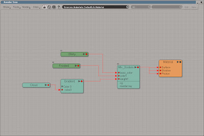

 Press the Run button in Script Editor to execute the script. Open the Bilboard PPG and playback the animation while changing the Time_Delay slider.


