Your online Softimage Educational Resource

The blog has been online for more than 4 years and there’s still not a single post even remotely related to the delicious brew called coffee… Perhaps it will someday, but in the meantime you can read the articles about Softimage. Most of the material are tutorials and Q&As I’ve written for 3D World Magazine sometime between today and 2003. If you have any questions please don’t hesitate sending me an email.


Thanks to Letterbox Animation Studios for hosting all the scene files.

Make sure you visit their Redi-Vivus.com for 100s of hours of free XSI video tutorials.

Sunday, June 28, 2009

Replace object A with a random new object


You’ve spent countless nights trying to finish the project on time and you’re just about to hit that sweet render button when the brilliant client comes through the door. He has just decided that he doesn’t want the landscape of cubes any more; he wants a random mixture of spheres, orbs and globs. Then he leaves you with the inspiring task of replacing the whole scene. A scenario that sadly isn’t all that uncommon. Though there’s no need to despair, with the solution below you should be home long before bedtime.

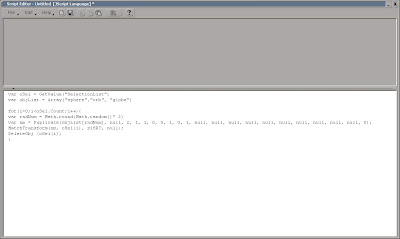
Open the scene spheres.scn from this issues CD. Press [Alt] + [4] to open the Script Editor and from the File menu choose Preferences... Change the Scripting Language to JScript and check the Log Commands checkbox. Close the PPG. Now, let’s have a quick look at the ingredients that you’ll be using in the script. Select an object, press [Ctrl] + [D] to create a duplicate, from the MCP > Transform menu choose Match All Transforms and pick any object. Then press [Del] to delete it. The script editor has just logged all the commands you need. The next step is to add which objects to replace, which objects that will be used to replace them and a random function that will choose one of these objects. The final script will look like this.


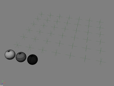
Since the script picks one of the three objects randomly, you can run the script again if you’re not happy with the distribution after the first run.


The project files used in this tutorial can be found at:
http://www.Redi-Vivus.com/Caffeineabuse/Random_Replace.zip


Quick tip
Change the Duplicate command to Clone (or Instantiate if you’re using models) to create clones of the replacing objects instead of duplicates.


Read the full post>>

Wednesday, June 10, 2009

Model the threads on a bottle in Softimage

Step 01
Create a single polygon
Once broken down to individual steps the procedure for creating the thread for the bottle, or any thread for that matter, is essentially a no-brainer. Rather than adding thread onto the existing geometry, you’ll create the tread as a separate piece and then weld it together with original object. The first step is to create a flat polygon with the same length as the circumference of the neck of bottle and with the preferred height of one revolution.


Step 02
circumference = π * diameter
Knowing the diameter of circle you can calculate the circumference using the formula: circumference = π * diameter (who knew those dull math lessons during compulsory-school would actually pay of one day.) Once the flat polygon is in place you’ll need to split it diagonally from top left to bottom right. The next step is to divide the thread (the currently flat polygon) to match the number of vertices on the bottle. Then simply duplicate the object as many times as want turns on the thread.


Step 03
Bend 360
Merge the objects together to create a single mesh and bend it 360 degrees to form a cylinder. Weld the seam and delete the perpendicular edges. Select the edge loop forming the tread, duplicate it and then delete the original loop. Select the new polygon loop and extrude it to create the tread. Merge the two objects together and you’re done. Don’t worry if you missed a part of the procedure, the full video capture can be found on this issues CD.

The project files used in this tutorial can be found at: http://www.redi-vivus.com/Caffeineabuse/Bottle_Threads.zip


Read the full post>>

Monday, June 1, 2009

Creating procedural X-ray shader in XSI

Using a 3d texture, such as the cloud texture, adds the so important irregularity to the material and ensures that it will line-up perfectly on all three axis.

Röntgen ray, or X-ray as it’s commonly known as, is a form of electromagnetic radiation. Its short wavelengths are capable of penetrating the soft tissue as well as the bones in the human body, which has made it very useable in the modern medical services. Nevertheless, the number one use of X-ray is probably in science fiction TV shows and 3d animation.

Start by open the scene xray.scn from this issues DVD. Select one of the vertebras and press [7] to open a Render Tree (they already have a constant shader applied). The first task is to make the objects transparent. For this you’ll need Gradient (Nodes > Mixers) to control the objects opacity, an Incidence (Nodes > Illumination) to control the mapping of the gradient and a Cloud texture (Nodes > Texture Generators) to brake up the uniformity. Open the gradient PPG and click the Black/White Preset button to clear the gradient and then add a new color marker approximately in the middle of the slider. Close the PPG and connect the Incidence to the input of the Gradient node and the Gradient to the scaletrans input of the Constant node.

From the Nodes > Texture Space Generators menu choose Projection. Connect the Projection node to the coord input of the 3D_cloud and the 3D_cloud to the color3 input of the Gradient node. Open the Projection PPG. Click the New button and choose Spatial. In the UV Remap section, change the Maximum on all three axis to 3 and close the PPG. Open the 3D_cloud PPG and set the Color 2 to black and lower the Contrast to 0.5.

From the Nodes > Image Processing menu, get an Invert node. Connect the Gradient to the input of the Invert node and the Invert node to the incandescence input of the Constant node. Open the Constant PPG and set the Color to a green color such as, R:0.4, G: 0.6, B: 0.4. Switch to the Transparency tab and set the transparency color to R:0.9, G: 0.9, B: 0.9. Switch to the Indirect Illumination tab and set the Incandescence Intensity to 0.3.

From the Nodes > Volume menu, get a Constant Density node, connect it the Volume input of the Material Node and open its PPG. Change the Transmit color to black and set the Unit Scale to 1:1.

The transparency can be modified with the Incidence node or the gradient node as well as the color sliders in the Constant shader. This ought to be enough for all your x-ray needs.

The project files used in this tutorial can be found at: http://www.redi-vivus.com/Caffeineabuse/XRay.zip

Quick tip
To see the effect of a specific node you can temporary connect it directly to the Surface input of the material node. Just don’t forget to reconnect the right node when you’re done.


Read the full post>>