

Image 01
For the reason that the relation between the crankshafts rotation and the pistons y position isn’t linear, a standard position constraint won’t cut it.
The concept of a reciprocating engine, commonly referred to as a piston engine, is in fact quite simple. Petrol gets injected into the cylinder and the piston pushes upwards to compress the petrol (fumes). The spark plug sets of a spark which ignites the fumes and causes it to explode. The force of the explosion sends the piston down through the cylinder. The piston is connected to the crankshaft via a connecting rod, which transforms the up and down movement into a rotation motion which in the end drive the wheels of the car. The piston is connected in pairs so when one piston is pushed down the other is pushed up which compresses the fumes, which is then ignited by the spark plug and so on.
The problem when recreating the setup in 3D is that the piston’s y position is not linear connected to the rotation of the crankshaft. The piston will move at different speed during a full rotation. Start by opening the scene Piston_Engine.scn from this issues CD. Select the piston and press [Ctrl] + [K] to open its local transform PPG. Right click on the animation icon (the green divot) for the Y Pos and choose Expression Editor… from the menu. Since you know the length of the of the connecting rod, 11 units, and the radius of the crankshaft, 1.5 units, getting the pistons Y position is merely a task of putting your high school trigonometry knowledge into practice.
Side a is calculated by multiplying c (the radius of the crankshaft) with cosines alpha. Before you can determine side d you have to calculate side b, which is done by multiplying c (the radius of the crankshaft) with sinus alpha. Once b is known you can use the Pythagorean theorem,
d2 + b2 = e2 => d= square root(e2-b2)
The full height (h) is sum of a + d
Enter the following expression in the editing pane, press the Apply button and then close the Expression Editor.
1.5 * cos(Crankshaft.kine.local.rotz ) + sqrt( pow( 11, 2 ) - pow( 1.5 * sin(Crankshaft.kine.local.rotz ), 2 ) )
Aligning the connection rod can easily be done in the same manner as in the previous equation. Or you can simply parent the connection rod under the piston and make it point to the crankshaft by using a constraint. Select the ConnectionRod_Rotation, click the Parent button in the Main Command Panel and select the Piston with the middle mouse button to make it the child of the Piston. With the ConnectionRod_Rotation still selected, click the Constrain menu and choose Direction. Pick the Crankshaft_Center when prompted. In the Direction Constraint PPG –Y button to align the Connection Rod.
The project files used in this tutorial can be found at:
http://www.redi-vivus.com/Caffeineabuse/Piston_Engine.zip
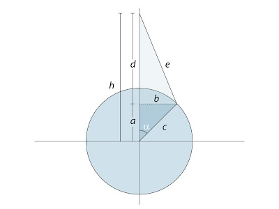 Image 02
A quick revisit to your high school trigonometry lessons is just want the doctor has ordered.
Quick tip
All the transforms are evaluated in local space, so to move or reorient the piston simply parent all the objects under a null (or any other dummy object) and you’re good to go.
Read the full post>>

