Your online Softimage Educational Resource

The blog has been online for more than 4 years and there’s still not a single post even remotely related to the delicious brew called coffee… Perhaps it will someday, but in the meantime you can read the articles about Softimage. Most of the material are tutorials and Q&As I’ve written for 3D World Magazine sometime between today and 2003. If you have any questions please don’t hesitate sending me an email.


Thanks to Letterbox Animation Studios for hosting all the scene files.

Make sure you visit their Redi-Vivus.com for 100s of hours of free XSI video tutorials.

Monday, December 29, 2008

Merry Christmas and a happy New Year!

I know i'm a but late with the holyday greetings, but I do have to work as well =) Nevertheless, I hope you’ve had a Merry Christmas and will have wonderful New Year!

I would also like to thank you for all the positive feedback comments I’ve received during the last couple of weeks. Please feel free to continue sending me any comments/suggestions/request you may have (click here to send me an email). I’ll be adding a couple of new articles once I’m back from the holidays so stay tuned for more tutorials.


Read the full post>>

Wednesday, December 10, 2008

Rigging Pixar-ish Eyes


It only takes between 90 seconds and four minutes from the moment you meet a new person to decide whether you fancy him/her or not. Though it’s natural to think that this decision above all is based on the verbal communication, it’s in fact very much the opposite. What the person is actually saying only accounts for seven per cent of your impression. The tone, rhythm and inflection accounts for another thirty-eight per cent, which mean that the remaining fifty-five per cent comes solitary from the body language; in which the eyes plays a very vital part. In addition, you only make eye contact in about 20 per cent of the time while talking to a person, so during the other 80 per cent your eyes will be doing something else. And no, we’re not talking about where teenage boys are looking when chatting with a pretty girl.

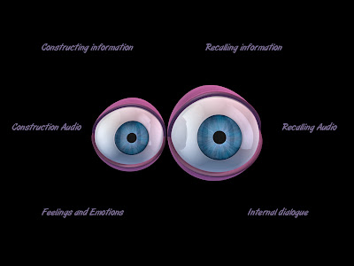
The eyes are very rarely still. In addition to inspecting the actual object/person in various patterns they flicker around, reflecting on what is said, thought, heard and felt. While these movements are very rapid and even subtle, they are very much present. When recalling information or past experiences we look to the left whereas when creating or making things up we look to the right. If you for example are trying to find inspiration or ideas for the hip project you’re currently working on you will look upwards, which is visual area. Then you start thinking about the great party you’ll be missing during the weekend because of the same project and that makes sad and you will look down, which is the emotional area. Right in the middle is the auditory area. So when you’re trying to form a sentence (in which you plea to get the Saturday off) you’ll look to the right but if you’re recalling a past conversation (I won’t even repeat what the project manager said the last time) you’ll look to the left. Naturally there’s a whole lot more to it than this, just as there’s a whole lot more to a successful cartoonish eye rig and animation that just hitting one or two good exaggerated shapes for the eyes.

At its most simplistic state, your rig must be able to do four things. Just as a real eye, you need to be able to look in different directions, change the size of the pupil as it reacts to the surrounding illumination and the characters emotions and avoid getting completely dried out by enabling it to blink. Since it’s a cartoon eye you certainly need to be able deform it into all sorts of interesting shapes. And naturally, you’ll need to be able to do all things simultaneously.

The project files used in this tutorial can be found at:
http://www.Redi-Vivus.com/Caffeineabuse/Pixar_Rigging_Eyes.zip

STAGE ONE The right look


Step 01
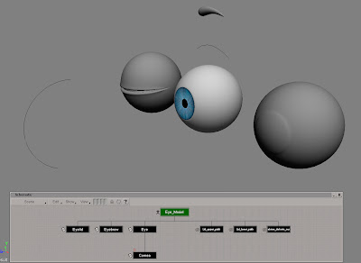
Start by opening the scene eye.scn from this issues CD. Apart from a couple of null objects, the scene contains all the objects needed (though several of them are hidden to avoid cluttering the viewports) to complete the following steps. For obvious reasons you’ll only deal with one eye during the walkthrough. Once completed, you can simply duplicate it and you’ll have a fresh pair of eyes.


Step 02
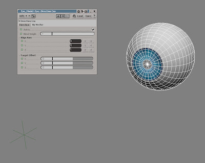
To control where the eye is looking, you’ll use separate object and constrain the orientation of the eye. From the Get > Primitive menu choose Null. Name it look_at and move it along the Z-axis so it’s well in front of the eye. Select the eye, click the Constrain button in the Main command panel (MCP) and choose Direction. In the Direction Constraint PPG, click the Z button in the Align Axis section to align the orientation of the eye.


Step 03
How and where you’re character is looking is essential not only to express different emotions, as discussed on the previous page, but is one of the key ingredients in bringing him or her to life. Make sure your character is focusing on something. It doesn’t matter if it’s an emotion or an actual object or if it’s on or off screen, just don’t’ leave him staring at nowhere completely without any movement.

STAGE TWO The pupil


Step 04
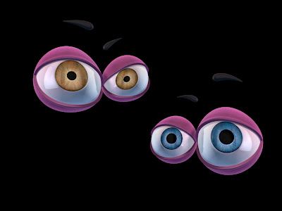
Lighting conditions and alcoholic beverage aren’t the only things that affect the size of the pupils. A cute and cuddly character will have big pupils but one that’s evil will have really small. In addition, if your character for example is looking at someone or something he fancies his pupils will dilate. If he on the other hand is looking at something he dislikes, they’ll contract.


Step 05
Press[2] to switch to the Animate toolbar. Select the eye and from the Deform > Shape menu choose Shape Manager... Change the display type to Shaded to get a clearer view of the object. Select the shape named Shape in the shape list and rename it to Eye_Default. With the shape still selected, press the Duplicate button and rename the new shape to Pupil_ Dilated.
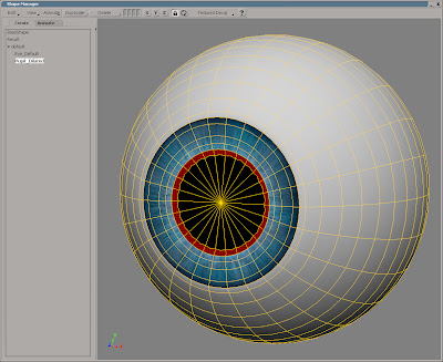


Step 06
Zoom in on the pupil and press [U] to switch to Raycast Polygon mode. Select the polygon loop at edge of the iris/pupil. Press [X] to activate the Scale tool and scale the polygons till the pupil is vastly larger. Note that you also may need to scale some of the adjacent points on the iris (so they don’t intersect) if you want to go really big with the pupil. Switch to the Animate tab and drag the slider to try the animation.

STAGE THREE In the blink of an eye


Step 07
It’s logical the assume that creating the blink would be a rather quick and easy thing to setup with two different shapes, one with the eyelids open and one with them closed. However, shape animation in XSI are interpolated in a linear fashion, which in this case mean that the eyelid would go straight trough the eye white instead of gradually covering the eye.


Step 08
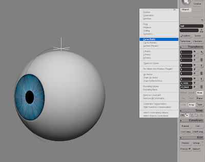
So, you’ll need use a slightly different approach. Press [8] to open an Explorer. Select the Lid_upper_path and the Lid_lower_path curves and press [H] to unhide them. Create a new Null object and name it Lid_upper_null1. With the null still selected, click the Constrain button in the MCP and choose Curve(Path). Pick the Lid_upper_path curve when prompted.


Step 09
Press [Ctrl] + [D] four times to duplicate the null object and then select all five null objects. In the Path Constraint PPG, switch to the Tangency tab and check the Active checkbox. Switch back to the Path tab and enter L(100) in the Path %age text box. This will distribute the null objects evenly along the curve (this is merely to demonstrate what you’ll be doing in the next steps).


Step 10
The idea is to create a relation between the nulls, so when you move the one at the end the others will automatically contract. Select the Lid_upper_null4 object (the second from the end of the curve). In the Path constraint PPG, right click on the animation icon next to the Path %age and choose Expression Editor… from the menu. In the Expression Editors editing pane, enter Lid_upper_null5.kine.pathcns.perc*0.75 and click the Apply button in the command bar.


Step 11
Select Lid_upper_null3, right click on the animation icon for the Path %age and choose Expression Editor… from the menu. Enter Lid_upper_null5.kine.pathcns.perc*0.5 and click the Apply button. Select Lid_upper_null2, repeat the previous steps and enter Lid_upper_null5.kine.pathcns.perc*0.25 in the editing pane. The last null will be used to smooth out the deformation on the eyelid, so leave it as it is.


Step 12
Create a new Null object, name it Lid_lower_null1 and path constrain it to the Lid_lower_path curve. Duplicate it three times (so there are four in total). Select the Lid_lower_null3 and apply the expression Lid_lower_null4.kine.pathcns.perc*0.66. Select the Lid_lower_null2 and apply Lid_lower_null4.kine.pathcns.perc*0.33. Now, whenever you change the Path %age for Lid_upper_null5 or Lid_lower_null4 the other will automatically follow.

STAGE FOUR Attaching the eyelids to the nulls


Step 13
Press [8] to open an Explorer, select the Eyelid and press [H] to unhide it. From the Deform > Envelope menu choose Set Envelope. Press Yes when asked about the construction mode and select the nine null objects. Right click to end the picking session. In the Automatic Envelope Assignment PPG, change the Number of Skeleton Objects to 1.


Step 14
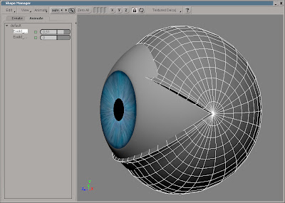
To see the effect of your weight editing, it’s a good idea to temporarily test moving the two nulls in charge of the deformation. Select the Lid_upper_null5 and Lid_lower_null4 and press the Selection button in the MCP. In the tree, expand the Kinematics > Constraints and click the icon in front of PathCns to open the PPG. Click the Lock icon to lock it in place. Now, simply drag the Path %age slider to blink the eye.


Step 15
The result isn’t half bad but it does need a bit of smoothing. However, you don’t want to smooth the weights on the entire object as this would produce undesired deformation in the corner of the eyelids. Select the eye and press [T]. Select all the points as shown in the above screenshot and from the Deform > Envelope menu choose Smooth Envelope Weights. Leave the values in the Smooth Envelope Weight PPG as they are and close it.

STAGE FIVE Deforming the eye


Step 16
Change the construction mode to Animation. By choosing in which mode you apply the different operators you can control in which order they are evaluated. By evaluating the blink before deforming the objects, you’ll make sure the entire lids stays outside the eye throughout the animation and align at the end of the blink. Select the Eye, the Eyelid and the Cornea.


Step 17
From the Get > Primitive menu choose Lattice. Set the X, Y and Z Subdivisions to 2. Close the PPG and open the Shape Manager. To see how the lattice is actually affecting the objects you’ll need to change a few settings. In the View menu, check the Display All Objects. In the Display Type menu, choose Display Options… Switch to the Display Mode tab and change the Construction History to Result (top).


Step 18
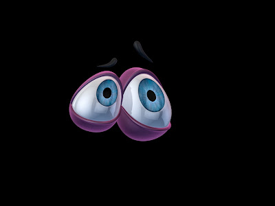
Select the default shape in the shape list and duplicate it. Name the shape Sad. In the Shape view, make sure the lattice is still selected, press [T] and move the points so the shape of the lattice resembles the above screenshot. Select the default shape in the shape list again and create three more duplicates. Name them Mad, Surprised and Relaxed and modify the respective shape to roughly match the screenshot in step19.


STAGE SIX Creating a custom control panel


Step 19
Switch to the Animate tab and play with the shapes and sliders to how well they play together. All the properties, shapes and operators that you’ll need to control the eye is currently scattered all over the scene, which isn’t very intuitive. Instead you can make use of Custom Parameter Sets, which essentially will function as a control panel for your eye.


Step 20
From the Create > Parameter menu choose New Custom Parameter Set and name it Eye_Control. Open an Explorer and select the Eye_Control node. Press [Shift] + [P] to add a new Custom Parameter. Enter Pupil_Dilation in the Parameter Name text box and press Ok. Create another six custom parameters and name them, Eyelid_Upper, Eyelid_Lower, Relaxed, Sad, Mad and Surprised.


Step 21
Press [Alt] + [0] to open the Animation Mixer (AM), and double-click on the Shape_ClusterClip to open it. Right click on the animation icon for the Sad_Clip and chose Expression Editor… Enter Eye_Model.Eye_Control.Sad in the Edit pane and click Apply. Repeat for the other three shapes. Click the Up button in the command bar of the AM. Double click on the next Shape_ClusterClip and enter Eye_Model.Eye_Control_Pupil_Dilation as an expression to the Pupil_Dilated_Clip.


Step 22
Open both the Path Constraint PPG for the Lid_lower_null4 and the Eye_Control PPG and click the Lock icons to keep them open. The eyelid requires a slightly different solution that the shape clips because you don’t want the sliders to just equal each other. Press [Alt] while dragging and dropping the animation icon for the Lower_Eyelid on to the animation icon of Path %age. This links the Path %age parameter to the Lower_Eyelid.


Step 23
Set the Lower_Eyelid to 0 (zero) and the Path %age to 30. Right click on the Path %age animation icon and choose Set Relative Values. Set the Lower_Eyelid to 100 and the Path %age to 100 and choose Set Relative Values again. Link the Path %age parameter for the Lid_upper_null5 to the Upper_Eyelid the same way.


Step 24
After playing a bit with the eye, trying to express different emotions and states of mind, you’ve probably noticed that you could really make use of a few more shapes. So return to the Shape Manager and once you’re happy with the shape library, it’s time to move on to the eyebrow. The eyebrow also plays an important part in creating strong expressions. Convenient enough, there’s an eyebrow included in the scene. The eyebrow is already deformed by a curve, so all you have to do is to create a couple of shapes for the curve, and connect their clips in the animation mixer to the custom parameter set in the same way as you did with the lattice.

Quick tip
Change the name of the custom property set to DisplayInfo_Eye_Control and activate Show Custom “DisplayInfo” Parameters in the Stats tab of the Visibility options in the camera viewport. The parameters are now available directly in the viewport.


Read the full post>>

Friday, November 28, 2008

Illustrating a Dandelion Clock


Even though you’re using geometry instead of the default hair strands, you are free to use any of the styling (and dynamics) tools available for hair grooming.
Start by opening the scene dandelion_clock.scn from this issues CD. For your convenience the scene already contains a stem and a seed object, so all you have to do is to add a bit of fluffiness to the seed before placing it on the stem and your done. Easy enough, right?

Start by selecting the seed object. Click the Clusters button in the Main Command Panel (MCP) and choose the Hair cluster. Press [Ctrl] + [2] to switch to the Hair Toolbar. From the Create > Hair menu choose From Selection. In the Hair property editor change the number of Total hairs to 25 or so. Switch to the Effects tab and change the Root Thickness to 1.2, the Tip to 0.2 and the Random scale to 0.2. Close the property editor. Click the Scale button in the Hair toolbar and scale the hair strands so they are approximately half the length of the seed.

With the hair object selected, press [7] to open a Render Three. From the Nodes > Hair menu choose Hair Geometry Shading. Connect the newly created node to the Surface and Shadow input of the Material node. Double-click on the Hair_Geo_Shading node to open the PPG. Check the Use Diffuse Gradient checkbox. Select the left marker and change the color to a pale grey (roughly RGB: 0.6, 0.6, 0.6) and select the right marker and set the color to almost white (roughly RGB: 0.9, 0.9, 0.9).

Close the PPG and the Render Tree and select the seed object. Press [Ctrl] + [G] to create a group and name it seed_instance. Select the stem and click the Cluster button in the MCP and pick the Head cluster. From the Create > Hair menu choose From Selection. There are usually somewhere in the region of 50 to 170 seeds per head, so change the number of Total hairs in the hair PPG to about 80 (for the sake of interaction you’ll only cover half of the head). Switch to the Instancing tab and check the Enabled checkbox. Click the Pick… button next to the Instance Group and pick the seed_instance group. Experiment with the hair styling tools (on both hair objects) to add some natural variation and you are done.
The project files used in this tutorial can be found at:
http://www.Redi-Vivus.com/Caffeineabuse/Illustrating_The_Dandelion.zip


You’re not limited to only using geometry for the hair instancing; hair objects can also be used.
Quick tip
The very same approach can successfully be used to create all sorts of vegetation, or to simplify the tedious task of covering trees and branches with leaves.


Read the full post>>

Tuesday, October 28, 2008

Particle Caching in Softimage XSI


Step 01
Caching the particles
Start a new scene and press [4] to switch to the Simulate Toolbar. From the Create > Particles > From Primitive menu choose From Grid. Under the Simulation tab in the Particles operator PPG change the Execution State > Mode to Standard Caching. Switch to the Output tab and set a unique name for the particle files. Go to the last frame in your animation to make sure you’ve cached the entire simulation. Select the particle cloud and press [H] to hide it.


Step 02
The Particle player
While the cached PTP files stores all the information for the particles position and orientation and so on they doesn’t store any information about the particle type (which includes how they’ll appear when rendered). To bypass this “little” problem you’ll need to load the cached files in the same scene as your original cloud. This way, the particle player will use the cached files from the hard drive but the ptype from the original cloud.


Step 03
Loading the cached files
From the Create > Particles menu choose From File. Browse to the simulation folder in your current project and select the cached particle files and click Ok. In the Particle Player PPG, set the Duration to match your simulation. Now, if you want to make any changes to your particles just unhide the cloud, make your changes and make sure you run the entire simulation. Hide the cloud again and the Particle Player is automatically updated.


Read the full post>>

Saturday, October 25, 2008

Animating Growing Vine


Wile the animation can easily come of as rather complicated it isn’t all that difficult to setup in XSI.

Start by creating a cone from the Get > Primitive > Polygon Mesh menu. Set the Length to 30 and the Base to 0.2. Increase the U Subdivisions to 12 or so and the V to 50. Name it Liana. Click the Center button in the Select menu and in the front viewport, move the object’s center all the way down to the bottom of the liana. This will create the effect of the liana growing from its base rather the center of the object. Since lianas usually don’t grow in perfectly straight lines, you’ll need to give it a bit more organic shape. From the Create > Curve menu choose Draw Cubic by CVs and draw a curve in the top viewport. Make sure you scatter the points a bit on all axes to give the liana a nice three dimensional flow. Now, select the liana object and from the Modify > Deform menu choose by Curve. Pick the curve when prompted. In the Curve Deform PPG start by switching to the Constraint tab and check the Constrain to Deformer checkbox. Switch back to the Curve Deform tab and change the Translation Along Curve so the liana lines up with the curve. Set the Scaling Along Curve to 0 and set a keyframe. Set a keyframe for the Roll parameter as well. Go to frame 100, set the Scaling Along Curve back to 1, the Roll to -145 set another keyframe on both parameters. From the Get > Primitive > Curve menu choose spiral. Set the Height to 20, the End Angle to 3600, the Start Radius to 0.25, the End Radius to 0.15 and finally the Subdivisions to 100. With the spiral selected, from the Modify > Deform menu choose by Curve and pick the same curve that is used to deform the liana. Change the Axis to Z, check the Constrain to Deformer checkbox and change the Translation Along Curve till they line up. Create another cone and make it longer but thinner than the first liana. Apply a Deform by Curve operator and pick the spiral curve. Animate in the same manner as the first liana.
The project files used in this tutorial can be found at:
http://www.Redi-Vivus.com/Caffeineabuse/Animating_Growing_Vine.zip
Adding a twist deformer, or any other deformer for that matter, to the liana before deforming it along the curve will add to the overall appearance of the animation.
Quick tip
To make the liana really stick to the surface of another object you can add a Shrink Wrap deformer to the curve. Change the projection to Closest Surface and lower the Amplitude to keep the objects from intersecting.


Read the full post>>

Symmetric modeling


Step 01
Clone your object
While there are a number of ways to (at least partly) do so, none of them are completely without flaws. However, don’t let this stop you from setting up one of your own. Select your (half) object and from the Edit > Duplicate/Instantiate menu chose Clone Single. Any changes made to your original object will automatically propagate to the clone but changes made to the clone object will not affect the original.

Step 02
Symmetrize the polygons
From the Modify > Poly.Mesh menu choose Symmetrize Polygons. This will mirror all the polygons, creating the missing half of the model. Press [Ctrl]+[4] to switch to the Palette toolbar and click the W button in the Display Types section. In the viewport or an explorer, pick your original object and then right click to end the picking session. This will set the objects display type to wireframe

Step 03
Easier interaction
In the Viewports menu bar > Display Types menu, uncheck the Override Object Properties. Select the clone. In the Select panel, click the Selection button and click on the Visibility node in the pop-up explorer. In the Visibility PPG uncheck the Selectability checkbox. This will keep you from unintentionally selecting it. Finally, open the Visibility PPG for the original object and uncheck the Render Visibility to prevent it from being rendered.


Read the full post>>

Modeling a bottle cap


The bottle cap is easily created by drawing a number of curves, each representing a different cross-section.
Regardless of the task at hand, the importance of good reference material can never be stressed enough. So, the only responsible thing to do in this scenario is to visit the closest pub for the ungrateful and cruel duty of gathering reference material.

Once you’re done (and hopefully sobered up a bit) start XSI and from the Get > Primitive > Curves menu choose Circle. You will need 4 points to create the shape of each tooth and you will need 21 teeth, so set the Radius to 1.25 and the Subdivisions to 84. Rotate it 90 degrees along the X-axis, press [Ctrl]+[D] to duplicate the circle and move it down 0.15 along the Y-axis. Now press [T] to set the selection filter to points and select every 4th point along the entire circle. Once selected, scale them about 1.06 along the local x and y axis’s so they’re just protruding the edges of the first circle. Duplicate the new circle and move it down another 0.1 units along the Y-axis. Press [T] to select the points again and scale them about 1.06 again. Click the Select button in the Main command panel and choose Invert Using Filter. Scale the new selection of points to about 0.98. Duplicate the circle again and move it down about 0.15 units along the Y-axis. Press [T] to select the points again and scale them about 1.01. Click the Select button and choose Invert Using Filter and scale the new selection 1.03. These are all very small values, but then again the teeth on the bottle cap aren’t big either so even the smallest adjustment will make a big difference. To create the top of the cap, select the first circle (the one which is perfectly round). Duplicate the circle, scale it down to about 0.93 and move it upwards 0.35 along the Y-axis. Create another duplicate, scale it down to 0.65 and move it upwards another 0.3 units. Create the the last duplicate and scale it to 0 (zero) and move it upwards another 0.05 units.

From the Create > Poly.Mesh menu choose Loft. Now pick the curve at the very bottom, then the one just above, etc till all the curves are selected. Right click to end the picking session. In the Loft PPG change the U and V span to 4 and you’re done.
The project files used in this tutorial can be found at:
http://www.Redi-Vivus.com/Caffeineabuse/Modeling_a_bottle_cap.zip
Since the loft operator is ‘live’, any changes made to the curves will automatically update the geometry as well.
Quick tip
By adding a bend deformer with low vales you can avoid the otherwise unnatural perfect look. Or you can use high values to actually fold the cap.


Read the full post>>

Thursday, October 9, 2008

Offset in Time


To change the offset of the stones, simply change the 0.08 value in the script editor and run the script again.
If you don’t have a deck of dominoes of your own, start by opening the dominoes.scn scene from this issues CD. Select the stone object, from the Main Command Panel > Constrain menu chose Curve (Path) and chose the dominoes_path curve when prompted. In the Path Constraint PPG, switch to the Tangency tab. Check the Active checkbox and click the –Z button to align the stone. Leave the PPG open, because you’ll return to it in just a few seconds. With the stone still selected, press [Shift]+[Ctrl]+[D] to open the Duplicate Multiple PPG. Enter 30 as the number of Copies and press OK. Press [8] to open an Explorer. Select the stone object, hold down [Shift] and select the stone30. This is important as the order in which the objects get selected will determine in what order they’ll get distributed. Return to the Path Constraint PPG and enter L(100) in the Path %age. This will distribute all the selected stones evenly along the curve. Once that is done you no longer need the path constraint, so with all the stones still selected chose Constrain > Remove All Constraints.

While you’re more than welcome to animate each stone falling onto the next and so on by hand, once you reach your second or third stone you’ll probably realize it just isn’t a viable solution. A more convenient approach is to animate a single stone and then pass on its animation to the others, each with the time slightly offset. Select the stone and set a keyframe for the rotation. Go to frame 4, rotate the stone -37 degrees on the X-axis (so the stone just touches the next stone) and set a new keyframe. Go to frame 15, rotate the stone to -82 degrees and set another keyframe. Next, press [0] (zero) to open an Animation Editor and change the slope handles on the fcurve to match the screenshot. Open an Explorer and select stone1 to stone30 and open the Script Editor. Enter the following lines and press the Run button. This will loop trough your selection and creates an expression which referencing the animation on the x-axis and applies an additional offset of 0.08 seconds for each stone.
The project files used in this tutorial can be found at:
http://www.Redi-Vivus.com/Caffeineabuse/Offset_in_Time.zip


Any changes made to the first stone’s animation will automatically change the animation of all the others, as their controlled trough an expression.

Quick tip
This approach is by no means limited to dominoes stones. The same expression can be used in numerous situations where you want to use the same animation on many objects, but offset them in time.


Read the full post>>

Wednesday, August 6, 2008

Cartoon Explosion

Even though it’s just about impossible to find a Hollywood blockbuster these days that doesn’t include its fair share of special effects and explosions, people just don’t seem to ever grow tired of them. On the contrary; take a poorly written excuse for a story, add a couple of nice, rich explosions and some other FX while you’re at it, and people will still see it. Let’s not single out a specific film because there’s just too many to choose from. Nevertheless, in all fairness sake, the sheer fun of blowing things up just might vindicate an otherwise totally uncalled-for explosion, or possibly even a bunch of them.

Without getting to scientific, let’s have a quick look at what we are about to create. Everything explodes differently, so depending on what’s causing it the result can range from a massive eruption of fireballs to a modest puff. Even so, they do share the same elemental course of events. The abrupt and violent release of energy sets of the explosion from a small or limited area and will aggressively grow larger. As the explosion or cloud travels away from the point of origin it loses its energy and will settle down and gradually fade away.

Due to the complexity and chaotic nature of explosions the majority seen in movies are in fact live footage rather than entirely computer generated images. Fortunately enough, creating a cartoonish style is very much about keeping things as simple as possible. Unless you have got way more spare time that is healthy for you, there’s a very limited chance that you’ll be adding that amount of details to 24 individual pictures per second when you are drawing them all by hand. After all, this is the style you are trying to mimic. Instead, the idea is to create a few basic shapes and distribute them over time with the help of XSI’s particle systems. Even so, you will still need to get a great deal of additions variation in there. To break-up the uniformity of the cloud even further, you’ll add animated textures to deform the geometry and shifting the colours.

However, before you can start blowing things up you will need to download and install the BA shader collection from www.binaryalchemy.de/. This set of free shaders is truly a ‘must have’ in any arsenal, whether your in the demolition business or not. So get to it, and let the fun begin…

The project files used in this tutorial can be found at:
http://www.Redi-Vivus.com/Caffeineabuse/Cartoon_Explosion.zip

STAGE ONE Creating the elements
Step 01
The two key elements to successfully create an explosion are the timing and the shading. By using a combination of geometry, animated textures, particles and these 24 steps you will get a good deal of control of both of them. From the Get > Primitive > Polygon Mesh menu chose Sphere. In the PPG, change the Radius to 10 and name it Flame.
Step 02
With the sphere still selected, click the Selection button in the Select panel and chose Geometry Approximation from the explorer. In the PPG, switch to the Displacement tab and change the displacement method to Fine and increase the maximum displacement (Max Displ.) to 6and Length to 1. Press [Ctrl]+[D] to duplicate the sphere. Change the name of the duplicate to Smoke.
Step 03
Press [Ctrl]+[D] again to create another duplicate and name it Blaze. Press [T] to change the selection filter to point, select all the points on the Blaze sphere and scale them to about 20 percent of their original size. Next, select each row of points and move them so the shape of the sphere roughly matches the above screenshot.

STAGE TWO Creating the material
Step 04
Select the Flame sphere and from the Get > Material menu chose Simple Toon Paint. In the PPG, check the Enable checkbox under the Ambience. Lower the Amount to about 0.3 and check the Shadows Only checkbox as well. Switch to the Highlights tab and lower the Diffuse Color to about R: 0.5, G: 0.5, B: 0.5. Uncheck the Iluminance checkbox and increase the Coverage to about 0.62. Switch to the Rimlights tab.

Step 05
While the rimlight commonly is used to brighten the silhouette of an object, you’ll the very opposite. Darkening the silhouette will help giving the effect of the flame burning with different temperatures as well as adding depth to it. In the Layer 1 section, check the Enable checkbox. Set the Color to R: 0.16, G: 0.16, B: 0.16 and change the Compositing method to Multiply. Lower the Coverage to 0.6 and set Softness to 0. Close the PPG.
Step 06
Press [Ctrl]+[7] to open a Render Tree. As the explosion detonates the flames will burn with a vivid yellow colour. Once they die out they should gradually turn into a gray cloud of smoke before eventually fading away. From the Nodes > Mixers menu, get a Mix 2 Colors node and connect it to the Surface input of the Toon_Paint node. Open the Mix_2colors PPG and set the colours as shown in the above screenshot.
Step 07
Instead of just fading the two colours, you will use of a texture to reveal the new colour and hide the old one. The difference may be subtle, but as usual - it is the small details that can make the big difference. From the Nodes > Textures menu chose More… In the browser, click the Paths button and chose Binary Alchemy Shader Collection - Essential. Pick the BA_fractal4d preset.
Step 08
Connect the BA_fractal4d node to the weight input of the Mix_2colors node and double click on the node to open the PPG. Start by setting all the colours except the color1 to pure white. To make the pattern actually grow through the sphere, you’ll animate the contrast of the colours rather than the colours them self. This will give the effect of gray smoke spreading across or covering the yellow flame surface.
Step 09
Go to frame 5 and click on the animation icon (the green dot) next to the Min in the Contrast section of the PPG. Go to frame 30, set the Min contrast to pure black and set a new keyframe. While the effect is good, the pattern is a bit too small or muddled. This can be fixed by changing the scale of the noise. Switch to the Texture Support tab and set the scale on all three sliders to 0.5. Return to frame 1.

STAGE THREE Adding puffiness

Step 10
It might be a bit difficult to fully see the effect of the material you’ve just created, but this is all about to change. By using a noise pattern to displace the geometry you’ll turn the smooth surface of the sphere into a puffy cloud in no time. From the Nodes > Textures menu chose More… etcetera, get a new BA_fractal4d node and from the Nodes > Math menu get a Change Range node.
Step 11
Connect the BA_fractal4d node to the Input input of the Change_range node and the Change_range node to the Displacement input of the Material node. Double click on the Change_range node to open the PPG. By remapping the default values, you’ll be able to push the geometry both inward and outward and as well as increase the amount of deformation. Set the New Range: Start to -5 and the New Range: End to 5.

STAGE FOUR Adding variations
Step 12
Open the BA_fractal4d PPG and check the Smooth edge checkbox.. Switch to the Noise tab. Click the animation icon next to the Time Red. Go to frame 50, set the time to 5 and set a new keyframe. Switch to the Texture Support tab. Change the Pre-Scale coordinate to Big Noise and all three scale sliders to 10. Go to frame 20 and click on the Scale animation icon to set a keyframe. At frame 50, set the scale to 1 and set a new keyframe.
Step 13
So you’ve completed the material for the flame sphere, but the Smoke and Blaze spheres could use some attention as well. Select the Blaze and the Smoke spheres and from the Get > Material menu chose Assign Material. When prompted, pick the Flame object to assign the same material these objects as well. Now, select only the smoke sphere and from the Get > Material menu chose MakeLocal Material.


Step 14
Update the Render Tree to make sure you have the material for Smoke sphere. Open the Mix2colors PPG and change the Base Color to R: 0.5, G: 0.5, B: 0.5. Open the PPG of the BA_fractal4d node controlling the Wight. Right click on the Min contrast animation icon and choose Remove Animation. Now, set the Min to RGB to 0 at frame 1 and set a keyframe. Change the RGB to 1 at frame 10 and back to RGB 0 at frame 40.


Step 15
In order for you to be able to use the geometry with the soon to be created particle systems, you’ll need to put them into different groups. So, select the Flame and the Smoke sphere and press [Ctrl]+[G] to create a group. Name it Blast. Next, select the Blaze sphere. Press [Ctrl]+[G] again to create another group and name it Detonation. Please feel free to use a more intuitive naming convention if you can think of one.

STAGE FOUR Creating the cloud


Step 16
Press [4] to switch to the Simulate toolbar. From the Create > Particles > From Primitive menu chose From Sphere. Select the PEmitter, rename it to PEmitter_Blast and from the Inspect > Emissions menu chose PEmitter_emission. Set the Spread and Var to 180. This will add a nice arbitrary variation to the emission. The next step is to create a sense of an underlying force, so change the Speed to 60 and the Var to 30.


Step 17
Set the Rate to 0 and click on the animation icon to set a keyframe. Go to frame 3, set the Rate to 80 and set new keyframe. Go to frame 10, set the Rate to 0 and set another keyframe. With the right mouse button, click on the animation icon and chose Animation Editor… from the menu. Select the keyframe at frame 10 and change the slope angle to -90, so that it’s pointing upward. Close the AE and return to the emission PPG.


Step 18
Switch to the Emission tab, change the name to Blast_emission and click the Edit button next to the ParType. Go to frame 1, set the Size to 0 and click the animation icon to set a keyframe. Go to frame 30, set the Size to 15 and set a new keyframe. Go to frame 100, set the Size back to 0 and set another keyframe. Switch to the General tab. Change the Size type to Age %. Please see the above screenshot for the rest off the settings.


Step 19
Switch to the Instancing tab. Check the Enable checkbox and click on the Pick… button. Pick the Blast group in the explorer. Change the Scaling to Non-uniform to particle. Switch to the Events tab and click the New Event button. Right click on the PType.PEvent and chose Inspect Item… from the menu. Change the Trigger condition to Particle Age % and set the Value to 20 and the Var to 2. Change the Action to Emit.


Step 20
In the Source section, click the Create button next to the Emission and then the Edit button. Now, in the PEvent_Emission PPG, press the New button next to the ParType. Copy the values shown in the screenshot above, both the one found in the PEvent_Emission > Emission section and those in the PType > General section. Don’t forget to change the Size type to Age %.

Step 21
At frame 1, set the Size to 0 and set a keyframe. Go to frame 30, set the size to 25 and set a new keyframe. Go to frame 100, set the Size to 0 and set another keyframe. Switch to the Instancing tab. Check the Enable checkbox and click on the Pick… button. Pick the Blast group again. Change the Scaling to Non-uniform to particle.

STAGE SIX Enhancing the detonation
Step 22
From the Create > Particles > From Primitive menu chose From Sphere. Select the PEmitter, rename it to PEmitter_Detonation and from the Inspect > Emissions menu chose PEmitter_emission. Go to frame 1, set the Rate to 0 and click the animation icon to set a keyframe. Go to frame 3, set the Rate to 200 and set a new keyframe. Next, go to frame 15, set the Rate back to 0 again and set another keyframe.

Step 23
Set the Speed to 170 and the Var to 30 and click the Edit button next to the ParType. Go to frame 1 and, set the Size to 0 and set a keyframe. Go to frame 5, set the size to 20 and set a new keyframe. Go to frame 100, set the Size back to 0 and set another keyframe. Switch to the General tab and copy the settings from the screenshot above. Don’t forget to check the Align on Velocity checkbox at the bottom of the PPG.
Step 24
Now, switch to the Instancing tab. Check the Enable checkbox and click on the Pick… button. Pick the Detonation group in the explorer. Change the Scaling to Uniform to particle to ensure that the Blaze sphere will keep the right proportions when scaled. The final step is to squeeze all the particles into a compact cloud. From the Get > Force menu chose Drag. Preferable in an explorer, select the both Clouds and from the Modify > Environment menu chose Apply Force and pick the drag object. Right click to end the picking session. To finish, select the three sphere objects and move them off-screen so that they don’t cover the explosion.


Read the full post>>