Your online Softimage Educational Resource

The blog has been online for more than 4 years and there’s still not a single post even remotely related to the delicious brew called coffee… Perhaps it will someday, but in the meantime you can read the articles about Softimage. Most of the material are tutorials and Q&As I’ve written for 3D World Magazine sometime between today and 2003. If you have any questions please don’t hesitate sending me an email.


Thanks to Letterbox Animation Studios for hosting all the scene files.

Make sure you visit their Redi-Vivus.com for 100s of hours of free XSI video tutorials.

Wednesday, August 6, 2008

Cartoon Explosion

Even though it’s just about impossible to find a Hollywood blockbuster these days that doesn’t include its fair share of special effects and explosions, people just don’t seem to ever grow tired of them. On the contrary; take a poorly written excuse for a story, add a couple of nice, rich explosions and some other FX while you’re at it, and people will still see it. Let’s not single out a specific film because there’s just too many to choose from. Nevertheless, in all fairness sake, the sheer fun of blowing things up just might vindicate an otherwise totally uncalled-for explosion, or possibly even a bunch of them.

Without getting to scientific, let’s have a quick look at what we are about to create. Everything explodes differently, so depending on what’s causing it the result can range from a massive eruption of fireballs to a modest puff. Even so, they do share the same elemental course of events. The abrupt and violent release of energy sets of the explosion from a small or limited area and will aggressively grow larger. As the explosion or cloud travels away from the point of origin it loses its energy and will settle down and gradually fade away.

Due to the complexity and chaotic nature of explosions the majority seen in movies are in fact live footage rather than entirely computer generated images. Fortunately enough, creating a cartoonish style is very much about keeping things as simple as possible. Unless you have got way more spare time that is healthy for you, there’s a very limited chance that you’ll be adding that amount of details to 24 individual pictures per second when you are drawing them all by hand. After all, this is the style you are trying to mimic. Instead, the idea is to create a few basic shapes and distribute them over time with the help of XSI’s particle systems. Even so, you will still need to get a great deal of additions variation in there. To break-up the uniformity of the cloud even further, you’ll add animated textures to deform the geometry and shifting the colours.

However, before you can start blowing things up you will need to download and install the BA shader collection from www.binaryalchemy.de/. This set of free shaders is truly a ‘must have’ in any arsenal, whether your in the demolition business or not. So get to it, and let the fun begin…

The project files used in this tutorial can be found at:
http://www.Redi-Vivus.com/Caffeineabuse/Cartoon_Explosion.zip

STAGE ONE Creating the elements
Step 01
The two key elements to successfully create an explosion are the timing and the shading. By using a combination of geometry, animated textures, particles and these 24 steps you will get a good deal of control of both of them. From the Get > Primitive > Polygon Mesh menu chose Sphere. In the PPG, change the Radius to 10 and name it Flame.
Step 02
With the sphere still selected, click the Selection button in the Select panel and chose Geometry Approximation from the explorer. In the PPG, switch to the Displacement tab and change the displacement method to Fine and increase the maximum displacement (Max Displ.) to 6and Length to 1. Press [Ctrl]+[D] to duplicate the sphere. Change the name of the duplicate to Smoke.
Step 03
Press [Ctrl]+[D] again to create another duplicate and name it Blaze. Press [T] to change the selection filter to point, select all the points on the Blaze sphere and scale them to about 20 percent of their original size. Next, select each row of points and move them so the shape of the sphere roughly matches the above screenshot.

STAGE TWO Creating the material
Step 04
Select the Flame sphere and from the Get > Material menu chose Simple Toon Paint. In the PPG, check the Enable checkbox under the Ambience. Lower the Amount to about 0.3 and check the Shadows Only checkbox as well. Switch to the Highlights tab and lower the Diffuse Color to about R: 0.5, G: 0.5, B: 0.5. Uncheck the Iluminance checkbox and increase the Coverage to about 0.62. Switch to the Rimlights tab.

Step 05
While the rimlight commonly is used to brighten the silhouette of an object, you’ll the very opposite. Darkening the silhouette will help giving the effect of the flame burning with different temperatures as well as adding depth to it. In the Layer 1 section, check the Enable checkbox. Set the Color to R: 0.16, G: 0.16, B: 0.16 and change the Compositing method to Multiply. Lower the Coverage to 0.6 and set Softness to 0. Close the PPG.
Step 06
Press [Ctrl]+[7] to open a Render Tree. As the explosion detonates the flames will burn with a vivid yellow colour. Once they die out they should gradually turn into a gray cloud of smoke before eventually fading away. From the Nodes > Mixers menu, get a Mix 2 Colors node and connect it to the Surface input of the Toon_Paint node. Open the Mix_2colors PPG and set the colours as shown in the above screenshot.
Step 07
Instead of just fading the two colours, you will use of a texture to reveal the new colour and hide the old one. The difference may be subtle, but as usual - it is the small details that can make the big difference. From the Nodes > Textures menu chose More… In the browser, click the Paths button and chose Binary Alchemy Shader Collection - Essential. Pick the BA_fractal4d preset.
Step 08
Connect the BA_fractal4d node to the weight input of the Mix_2colors node and double click on the node to open the PPG. Start by setting all the colours except the color1 to pure white. To make the pattern actually grow through the sphere, you’ll animate the contrast of the colours rather than the colours them self. This will give the effect of gray smoke spreading across or covering the yellow flame surface.
Step 09
Go to frame 5 and click on the animation icon (the green dot) next to the Min in the Contrast section of the PPG. Go to frame 30, set the Min contrast to pure black and set a new keyframe. While the effect is good, the pattern is a bit too small or muddled. This can be fixed by changing the scale of the noise. Switch to the Texture Support tab and set the scale on all three sliders to 0.5. Return to frame 1.

STAGE THREE Adding puffiness

Step 10
It might be a bit difficult to fully see the effect of the material you’ve just created, but this is all about to change. By using a noise pattern to displace the geometry you’ll turn the smooth surface of the sphere into a puffy cloud in no time. From the Nodes > Textures menu chose More… etcetera, get a new BA_fractal4d node and from the Nodes > Math menu get a Change Range node.
Step 11
Connect the BA_fractal4d node to the Input input of the Change_range node and the Change_range node to the Displacement input of the Material node. Double click on the Change_range node to open the PPG. By remapping the default values, you’ll be able to push the geometry both inward and outward and as well as increase the amount of deformation. Set the New Range: Start to -5 and the New Range: End to 5.

STAGE FOUR Adding variations
Step 12
Open the BA_fractal4d PPG and check the Smooth edge checkbox.. Switch to the Noise tab. Click the animation icon next to the Time Red. Go to frame 50, set the time to 5 and set a new keyframe. Switch to the Texture Support tab. Change the Pre-Scale coordinate to Big Noise and all three scale sliders to 10. Go to frame 20 and click on the Scale animation icon to set a keyframe. At frame 50, set the scale to 1 and set a new keyframe.
Step 13
So you’ve completed the material for the flame sphere, but the Smoke and Blaze spheres could use some attention as well. Select the Blaze and the Smoke spheres and from the Get > Material menu chose Assign Material. When prompted, pick the Flame object to assign the same material these objects as well. Now, select only the smoke sphere and from the Get > Material menu chose MakeLocal Material.


Step 14
Update the Render Tree to make sure you have the material for Smoke sphere. Open the Mix2colors PPG and change the Base Color to R: 0.5, G: 0.5, B: 0.5. Open the PPG of the BA_fractal4d node controlling the Wight. Right click on the Min contrast animation icon and choose Remove Animation. Now, set the Min to RGB to 0 at frame 1 and set a keyframe. Change the RGB to 1 at frame 10 and back to RGB 0 at frame 40.


Step 15
In order for you to be able to use the geometry with the soon to be created particle systems, you’ll need to put them into different groups. So, select the Flame and the Smoke sphere and press [Ctrl]+[G] to create a group. Name it Blast. Next, select the Blaze sphere. Press [Ctrl]+[G] again to create another group and name it Detonation. Please feel free to use a more intuitive naming convention if you can think of one.

STAGE FOUR Creating the cloud


Step 16
Press [4] to switch to the Simulate toolbar. From the Create > Particles > From Primitive menu chose From Sphere. Select the PEmitter, rename it to PEmitter_Blast and from the Inspect > Emissions menu chose PEmitter_emission. Set the Spread and Var to 180. This will add a nice arbitrary variation to the emission. The next step is to create a sense of an underlying force, so change the Speed to 60 and the Var to 30.


Step 17
Set the Rate to 0 and click on the animation icon to set a keyframe. Go to frame 3, set the Rate to 80 and set new keyframe. Go to frame 10, set the Rate to 0 and set another keyframe. With the right mouse button, click on the animation icon and chose Animation Editor… from the menu. Select the keyframe at frame 10 and change the slope angle to -90, so that it’s pointing upward. Close the AE and return to the emission PPG.


Step 18
Switch to the Emission tab, change the name to Blast_emission and click the Edit button next to the ParType. Go to frame 1, set the Size to 0 and click the animation icon to set a keyframe. Go to frame 30, set the Size to 15 and set a new keyframe. Go to frame 100, set the Size back to 0 and set another keyframe. Switch to the General tab. Change the Size type to Age %. Please see the above screenshot for the rest off the settings.


Step 19
Switch to the Instancing tab. Check the Enable checkbox and click on the Pick… button. Pick the Blast group in the explorer. Change the Scaling to Non-uniform to particle. Switch to the Events tab and click the New Event button. Right click on the PType.PEvent and chose Inspect Item… from the menu. Change the Trigger condition to Particle Age % and set the Value to 20 and the Var to 2. Change the Action to Emit.


Step 20
In the Source section, click the Create button next to the Emission and then the Edit button. Now, in the PEvent_Emission PPG, press the New button next to the ParType. Copy the values shown in the screenshot above, both the one found in the PEvent_Emission > Emission section and those in the PType > General section. Don’t forget to change the Size type to Age %.

Step 21
At frame 1, set the Size to 0 and set a keyframe. Go to frame 30, set the size to 25 and set a new keyframe. Go to frame 100, set the Size to 0 and set another keyframe. Switch to the Instancing tab. Check the Enable checkbox and click on the Pick… button. Pick the Blast group again. Change the Scaling to Non-uniform to particle.

STAGE SIX Enhancing the detonation
Step 22
From the Create > Particles > From Primitive menu chose From Sphere. Select the PEmitter, rename it to PEmitter_Detonation and from the Inspect > Emissions menu chose PEmitter_emission. Go to frame 1, set the Rate to 0 and click the animation icon to set a keyframe. Go to frame 3, set the Rate to 200 and set a new keyframe. Next, go to frame 15, set the Rate back to 0 again and set another keyframe.

Step 23
Set the Speed to 170 and the Var to 30 and click the Edit button next to the ParType. Go to frame 1 and, set the Size to 0 and set a keyframe. Go to frame 5, set the size to 20 and set a new keyframe. Go to frame 100, set the Size back to 0 and set another keyframe. Switch to the General tab and copy the settings from the screenshot above. Don’t forget to check the Align on Velocity checkbox at the bottom of the PPG.
Step 24
Now, switch to the Instancing tab. Check the Enable checkbox and click on the Pick… button. Pick the Detonation group in the explorer. Change the Scaling to Uniform to particle to ensure that the Blaze sphere will keep the right proportions when scaled. The final step is to squeeze all the particles into a compact cloud. From the Get > Force menu chose Drag. Preferable in an explorer, select the both Clouds and from the Modify > Environment menu chose Apply Force and pick the drag object. Right click to end the picking session. To finish, select the three sphere objects and move them off-screen so that they don’t cover the explosion.


Read the full post>>

Hydraulic Piston in XSI

While it’s the piston that is forcing the arms to move in reality, makes more sense doing the opposite when building it in 3d. Besides, the visual appearance will be exactly the same.

By looking at hydraulic pistons in action you’ll soon find there’s quite a lot things going on at the same time. When trying to recreate the same functionality in 3D, you’ll most likely become aware of it even sooner. As the arms, to which the piston is attached, moves the piston obviously needs to stay connected at both ends at all times. This is achieved by making it expand and contract. However, this will also change the rotation of the piston which is what makes the setup a bit complicated. While it is the hydraulic system that is driving the arm in reality, there’s really no point in creating the same setup in 3d since you’ll be animating by hand anyway. It’s far more intuitive to do it the other way around, animate the arm and make the piston follow the movement.

Open and examine the scene piston.scn which can be found on the included CD. For your convenience the hierarchy for the arm has already been created. All you have to do is to add the final touches. Use the Schematic View (hotkey [9]) to get an overview of all the elements in the scene. Start by making the Piston_upper object a child of Piston_upper_rot and the Piston_lower object a child of Piston_lower_rot. Next, make Piston_upper_rot and Piston_upper_target children of upper_arm and Piston_lower_rot and Piston_lower_target children of lower_arm. Select the null object named Piston_upper_rot. From the Constrain menu choose Direction and pick the null named Piston_lower_target. Now, select the null named Piston_lower_rot and apply a Direction Constraint and pick the null named Piston_upper_target. If you where to constrain the Piston_upper_rot directly to the Piston_lower_rot and vice versa you would get an evaluation cycle as they would depend on each other. While you can get away with cycles in some situations, you’re better of getting into the habit of avoiding them as they’ll then never become a problem later on. Now, whenever you rotate the arms the piston will automatically expand and contract as well as maintaining its correct rotation.


The project files used in this tutorial can be found at:
http://www.Redi-Vivus.com/Caffeineabuse/Hydraulic_Piston_in_XSI.zip


Avoid creating cycles with the direction constraints by using different nulls for the targets and the ones controlling the rotation

Quick tip
An alternative way of controlling the arms is to make use of a 2 bone chain. Parent the upper_arm under the first bone and the lower_arm under the second bone. (example scene included on the CD)


Read the full post>>

Studio Lighting

There’s a certain irony involved when people enquire about photorealism because, apart from the spelling, there isn’t really anything ‘real’ about it. What we perceive as being ‘realistic’ in an image (or an animation, for that matter) has more to do with whether it’s consistent with our expectations of it, rather than whether it’s truly representative of the real world. Over time, we get used to certain motifs being rendered in a certain way, and any deviation from this stands the risk of being regarded as strange or unnatural. As an extreme example, imagine Godzilla painted in vibrant pink and yellow stripes. No matter how good the paint job is, or how cute he looks, the effect would still look slightly odd, to say the least.

Another important point to note is that whenever we look at a photograph, we’re not actually looking at reality itself, but a representation of it. Even though variables such as f/stop (focal ratio, or depth of field), motion blur, camera lenses, different film types and grain don’t exist in the world around us, we could rationally claim that the image we’re scrutinising is unrealistic if any of these variables are absent. In effect, we have to mimic not only reality but the equipment used to ‘capture’ it.

Given that realism is about a whole lot more than just activating the switch that simulates the light bouncing around in your scene, the following walkthrough sets out a selection of techniques for an effective final gathering workflow, including how to use FG in combination with ambient occlusion. The procedures can be further refined, and can be used all at once or separately, depending on your requirements. For now, pour yourself a new cup of coffee (purely as reference material, of course) and let’s get started.

The project files and the original tutorial as it appeared in 3D World can be found at http://www.computerarts.co.uk/tutorials/3d__and__animation/3d_worlds_question_of_the_month

It appears that the article and project files has been moved and is no longer available at the above address. If you want to download the project files, please use this link instead: http://dl.dropbox.com/u/3834689/CaffeineAbuse/StudioLighting.zip


Part 1 Shades of gray
Step 01
Start by open the coffeecup scene. The first thing we’ll need to do, which you should always do with any scene, is turning of the ambience light as this gives a flat and unrealistic illumination. Next, open an Explorer (shortcut [8]) and delete the default light as well. Your scene is now completely black so any illumination will have to be created, and more importantly, controlled by you.
Step 02The lighting is difficult enough without having all the textures and materials complicating things further. At this stage you’re really only interested in getting the illumination to play properly so any redundant information in the image may cause unnecessary distraction. Nevertheless, a very common “mistake” made by a lot of 3d artist, is to set up the lights in a fully textured/shaded scene.
Step 03
Seeing that the cups already have individual colors applied to them, you don’t want to modify their actual materials. Instead, you can temporarily override their local materials by putting the cups in a new Partition and apply a shader to the partition. So, select all the cups and press [3] to switch to the Render toolbar.
Step 04From the Pass > Partition menu chose New Partition. With the partition still selected, click Get >Material and pick Lambert. Set the RGB values for both the Diffuse and Ambient to 0.5 to ensure a neutral color. By limiting the objects to be lit in your scene to shades of gray, it will be a whole lot easier for you see the effect of the color and intensity of each light.

Step 05
Apart from certain situations, the very purpose with your lights are to make you objects visible in a otherwise completely black environment. However, a well lit scene does more than just illuminate your objects, it defines them. While you’ll most likely strive to keep your models as smooth as possible in your final image, you can do the opposite as you’re setting up the lighting,
Step 06
Again, with the partition still selected, click Get > Property > Geometry Approximation and switch to the Polygon Mesh tab. Each of the coffee cups is made by a number of polygons, which will be rendered as either smooth or faceted depending on your discontinuity settings. Set the Angle to 0 (zero) to ensure that the polygons will be rendered completely flat (you’ll se why in just a minute).

Part 2 Let there be light
Step 07
The idea is to start from a three point lighting setup, and refine it as you advance. But instead of the standard lights you’ll use 3D geometry with differently colored constant materials applied to them. As you progress trough the following steps, make sure to frequently draw a render region to se the effect each adjustment has to the scene
Step 08
You do need at least one light for the Final Gathering (FG) to work, so start by creating a standard Spotlight from the Get > Primitive > light menu. Position the spotlight approximately at X: 6, Y: 3, Z: 0, set the Color to RGB 0.83, 0.88, 0.93 and the Intensity to about 0.4. Next, open the Render Options PPG (Render > Region > Options…). Switch to the FG tab in the PPG and check the Final Gathering checkbox to enable it.


Step 09
Increase the number of Bounces to 2. You can leave the rest of the settings for now. When it’s time to render the final image you can increase the Accuracy to 200 (or more), set the Min Radius to 0.2 and the Max Radius to 1. Let’s start creating the lights. From the Get > Primitive menu chose Sphere and change the setting according to the accompanying screenshot.


Step 10
Rotate and position it just behind the spotlight. Apply a Constant shader and set the RGB to 2, 2.2, 2.5. Duplicate the sphere, make it slightly smaller (see next screenshot for how to position the spheres). Click Get > Material > MakeLocal Material and change the RGB to 1.99, 2.0, 1.57. Duplicate the sphere once again, make it larger and click Material > MakeLocal Material. Set the RGB to 3.5, 3.5,3.5 .
Step 11
With all the lights roughly in place it’s time to fine tune their position and intensity, and this is where the flat polygons will be of great assistance. To get the most out of your light setup, strive for each of the cups’ polygons to have a slightly different shade than the adjacent. While you should work with one light at the time, seeing that you’re using final gathering, modifying one of them affects the entire scene.
Step 12So for that reason you should work by going back and forth, making small changes each time. Note that the Accuracy and Radius settings in the render PPG also affect the illumination of the scene and not just the quality. Once you’re satisfied with the lighting, ether delete the partition (holding the overrides) or create a new Pass to revert to the cups original shading and materials.

Part 3 Ambient occlusion
Step 13
Even though you’re using FG to illuminate your scene, combining it with a subtle effect of Ambient Occlusion will place the cups on ground and add to the overall depth and richness of the image. From the Pass > Edit > New Pass menu choose Empty. Select all the cups and the ground object and from the Pass > Partition menu choose New Partition.
Step 14
With the partition still selected apply any shader from the Get > Material menu and press [7] to open a Render Tree. Click Nodes > Illumination > Ambient Occlusion (AO) and connect the node to the Surface input of the Material node. Open the AO PPG and change the setting according to the accompanying screenshot. Open the Background_Objects_Partition’s PPG and set the Render Visibility to Hide Members.


Step 15
Once happy with the AO shader as well, it’s time to hit the longed-for render button. Note, as you’ll be doing a fair amount of adjustments to the mages, render them in 16 bit depths (using the .sgi file) instead of the default 8 bit. This will ensure the quality to hold throughout production. You should also render the images at a slightly larger resolution as the edges in the final image will need to be cropped.

Part 4 Adding mattes


Step 16While the need for mattes may not be critical in this scenario, it can be the difference between a couple of minutes work in compositing or having to re-render an entire sequence. From the Pass > Edit > New Pass menu choose Empty and name it mattes. From the Pass > Partition menu, create three New Partitions and name them red, green and blue_matte.
Step 17
Select the partition named red_matte and apply a constant shader. Set the RGB to 1,0,0. Apply a constant shader to the green and blue_matte as well, and set the RGB to 0,1,0 and 0,0,1. Select all the blue cups and, in the Explorer, right click on the red_matte portion and chose Add Selected Objects. Next, add the violet cups to green_matte and the turquoise cups to the blue.
Step 18
Open the Background_Objects_Partition’s PPG and set the Render Visibility to Hide Members. Set the rendering output and format to the same as in the two previous passes and hit Render. Once completed, go to the View > Layouts menu and switch to Compositing. If you’re using XSI Foundation, you can use Photo Shop to composite and edit the images.
Part 5 Compositing using the FX Tree
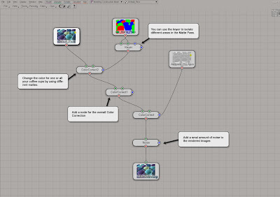
Step 19In the FX Tree menu, chose Passes > Get All Passes to automatically import the rendered images into the FX Tree. Add and connect the operators to match the accompanying screenshot. Please see the full-size screenshot on the CD for further explanation of the operators’ different settings.


Step 20When compositing the shadows or ambient occlusion, people often simply add the images and set the blending mode (Math Op in the FX Tree) to multiply. However, shadows aren’t black at all but rather absence of light. So for a more subtle and realistic result you should add a color corrector to the image and use the shadow/AO image as matte to limit the effect.
Step 21
As discussed in the introductory text, effects such as dept of field can bring your computer to its knees if applied in the previous stage unless you’ll settle for the 2d version. However, there’s another way. Open the FileOutput operator and render the composite. Once saved to disk you can project the very same image back into your 3D scene. From the View > Layouts menu, switch back to the Default layout.

Part 5 Depth of Field
Step 22
From the Pass > Edit > New Pass menu choose Empty. Name it Depth of field. Open an Explorer and set the scope to Passes. Select the Background_Objects_Partition in your new pass and apply a Constant shader. Click on the Connection icon and chose Image. Click the New button and pick the image you just rendered from the FX Tree. In the Texture Projection section, click New and chose Camera Projection.
Step 23
In the Explorer, pick the Camera. Select the camera and press [Enter] to open the camera PPG. Switch to the Lens Shader tab, press the Add button and pick the Depth_of_field shader. Select the very same in the shader stack (the list) and press the Inspect button. Determine which value to enter to get the focus exactly where you want it, let alone animating it, can be a bit tricky if you’re doing it by hand…
Step 24
…so, let’s use an expression instead. From the Get > Primitive menu pick Null and name it dof_focus. Return to the dof PPG and right click on the animation icon next to Focal Distance in inches and chose Expression Editor… from the menu. In the Editing Pane (the white area) enter ctr_dist_cam(dof_focus.) and press the Apply button. The expression ensures that the focus will always be spot on the null’s location. Now, play with the nulls position and the Depth of Field Strength parameter in the dof PPG till you’re satisfied with the result. Render the final image and you’ve just earn yourself another cup of that sweet, delicious, irresistible coffee. Make sure you enjoy every drop…


Read the full post>>