
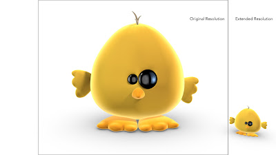
By changing the cameras position and increase the size of the output resolution you’ll obviously be able to widen the shot. Unfortunately you’ll end up with a completely different perspective. By compensating the cameras field of view angle in relation to the added pixels the expanded images will line up exactly with the original image when superimposed. The procedure will work just as well if you need to reduce the size of the image.
 Step 01
Determine the scaling factor
For example let’s assume that your original rendered image is 800 pixels wide and you would like to add 200 pixels to each side making it 400 pixels wider in total. To determine the scaling factor simply divide your desired resolution with the original, which in this scenario is 1200 (800+400) by 800 which equals a scaling factor of 1.5.
 Step 02
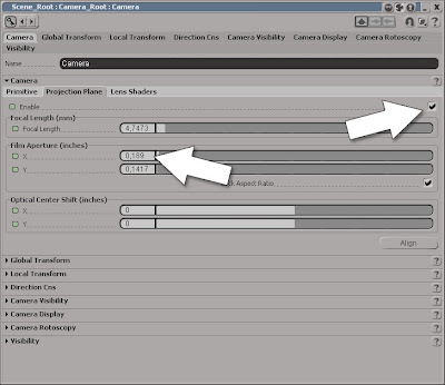
Changing the Film Aperture
In the Camera viewport, click on the Camera icon menu button and choose Properties from the menu to open the Cameras PPG. Switch to the Projection Plane tab and check the Enable checkbox. Please note that depending on whether you want to increase the width of the image or the width and the height you’ll need to check or uncheck the Lock Aspect Ratio checkbox in the Film Aperture section prior to changing its values.
 Step 03
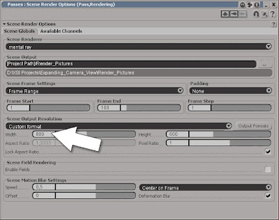
Changing the output resolution
In the Film Aperture X text box enter 1.5* (which is the scaling factor) and press [Enter] to multiply the original value. Close the PPG and press [3] to switch to the Render Toolbar. From the Render > Render menu choose Scene Options… to open the PPG. In the Scene Output Resolution section enter 1.5* in the Width textbox and press [Enter]. Don’t forget to check/uncheck the Lock Aspect Ratio here as well prior to multiplying the values.
Step 01Determine the scaling factor
For example let’s assume that your original rendered image is 800 pixels wide and you would like to add 200 pixels to each side making it 400 pixels wider in total. To determine the scaling factor simply divide your desired resolution with the original, which in this scenario is 1200 (800+400) by 800 which equals a scaling factor of 1.5.
Step 02Changing the Film Aperture
In the Camera viewport, click on the Camera icon menu button and choose Properties from the menu to open the Cameras PPG. Switch to the Projection Plane tab and check the Enable checkbox. Please note that depending on whether you want to increase the width of the image or the width and the height you’ll need to check or uncheck the Lock Aspect Ratio checkbox in the Film Aperture section prior to changing its values.
Step 03Changing the output resolution
In the Film Aperture X text box enter 1.5* (which is the scaling factor) and press [Enter] to multiply the original value. Close the PPG and press [3] to switch to the Render Toolbar. From the Render > Render menu choose Scene Options… to open the PPG. In the Scene Output Resolution section enter 1.5* in the Width textbox and press [Enter]. Don’t forget to check/uncheck the Lock Aspect Ratio here as well prior to multiplying the values.
Read the full post>>


