Your online Softimage Educational Resource

The blog has been online for more than 4 years and there’s still not a single post even remotely related to the delicious brew called coffee… Perhaps it will someday, but in the meantime you can read the articles about Softimage. Most of the material are tutorials and Q&As I’ve written for 3D World Magazine sometime between today and 2003. If you have any questions please don’t hesitate sending me an email.


Thanks to Letterbox Animation Studios for hosting all the scene files.

Make sure you visit their Redi-Vivus.com for 100s of hours of free XSI video tutorials.

Wednesday, December 23, 2009

Problem Downloading project files

There seems to be a slight problem downloading the project files for the tutorials. Please let me know if you experience this and I’ll send you the files via email…


Read the full post>>

Merry Christmas and Happy New Year!

Just wanted to wish you all a merry Christmas and a happy New Year! While I haven’t much time lately to add more articles there are some goodies waiting to be published, so stay tuned…


Read the full post>>

Thursday, December 3, 2009

Animating a cable using Softimage cloth


The project files used in this tutorial can be found at:
http://www.redi-vivus.com/Caffeineabuse/Cable_Using_SoftimageCloth.zip


Softimage Cloth
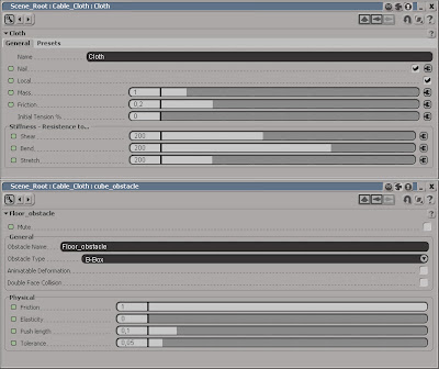
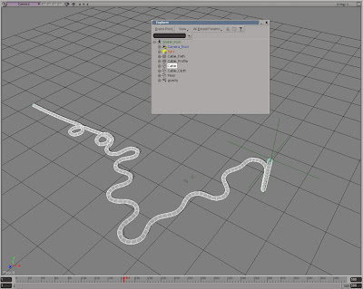
Start by open the scene cabel.scn from this issues CD. Select the Cable_Cloth object and press [T] to set the selection filter to points and select the two vertices at the right end of the object. From the Edit menu choose Create Cluster with Center. Press [4] to switch to the Simulate Toolbar. Select the Cable_Cloth object and from the Create > Cloth menu choose From Selection. Different types of cables obviously has different characteristics. Use the values in the above screenshot as a starting point and experiment on your own.

Local Cloth Cluster
Now, select the two vertices again and from the Create > Cloth menu choose Local Cloth Cluster. Make sure you check the Nail checkbox in the Cloth PPG. Select the object again and from the Get > Force menu choose Gravity. Select the Cable_Cloth again and from the Modify > Environment menu choose Set Obstacle. When prompted, pick the Floor object. Right click to end the picking session. In the Floor_obstacle PPG increase the friction to 0.8 or so to stop the cable from sliding all over the place. Set the Push length to 0.1 to compensate for the cable’s thickness.

Extract from edge
Select all the edge along one side of the cloth object. Press [1] to switch back to the Model toolbar and from the Create > Curve menu choose Extract from Edges. This creates a separate curve object from the selected edges and because it’s a live operator the cloth simulation will automatically be propagated as well. Name the curve Cable_Path. From the Primitive > Curve get a Circle and set the Radius to 0.05. From the Create > Poly.Mesh menu choose Extrusion Along Curve and pick the Cable_Path curve when prompted. Animate the Null object and your cable will follow perfectly.


Read the full post>>

Wednesday, July 15, 2009

Facial rig in Softimage XSI

After successful thesis such as cogito ergo sum ("I think, therefore I am"), the prominent French 17th century philosopher and scientist René Descartes came to the conclusion that the mind and body where separated from one and other. 400 years later we know that nothing could be more wrong. In fact, you can’t have a single thought without a bodily reaction. The second you have one, the brain cells starts working frenetic and sends signals all over the place including to the autonomous nervous system. The ANS generally performs without us being aware of it and controls functions such as the hart and respirators rate, perspiration, sexual arousal (okay, this you might be aware of) and the diameters of the pupils. So even without utter a single word your body may very well be screaming.

Only 10-15 percent of the communication between persons are based on what they are actual saying, the remaining 85 percent is communicated nonverbal. This includes everything from the body language, emotional state, and the tone of your voice to the size of your pupils. Your subconscious constantly process and analyses all of this information and when this contradict the words you’re saying, people will immediately detect there’s something wrong.

One of the more perceptible ways of nonverbal communications is the use of facial expressions. The complex anatomy of the human face enables us to pull thousands of different expressions, each with its own meaning. Fortunately, you don’t have to recreate every single one of them to bring your characters to life. There are seven different groups of emotions or expressions that are universal, meaning we express them in the same way regardless of where we live on the planet or our cultural preferences. These fundamental emotions are: joy, sadness, surprise, fear, anger, disgust and contempt. All of these, as well as the ability to interpret them, are inherited by birth and isn’t something you learn as you go trough life. Your digital character is different story though.

Whether you need countless individual sliders controlling every aspect of the face, or if you can make do with a series of predefined shapes really depends on the complexity your animation. Facial rigging can easily become over-ambitious and there’s even a good chance you start to lose control as the number of shapes and sliders simply grows out of hand. With the use of some intuitive controls you’ll probably need far less than you originally thought.

The project files used in this tutorial can be found at: http://www.Redi-Vivus.com/Caffeineabuse/FaceRig.zip

STAGE ONE Get in shape

Step 01
Start by opening scene Face_Start.scn from this issues CD. The scene (unsurprisingly) contains an enveloped head, a skeleton and a pair of eyes. All you need for an exciting 24 step walkthrough basically. The first step is to create all the individual shapes for your character. Well, that’s not entirely true. You’ll only create the expressions on one half of the face and then mirror the shapes to create the shapes for the other half. So it’s half the work but twice the fun.

Step 02
Select the head and from the View > Animations menu choose Shape Manager. For the purpose of demonstration you’ll divide the face in two sections, the eyes and the area surrounding it and the mouth. This probably isn’t something you want to do in a more advanced facial rig since you want to attain as much flexibility as possible, thus splitting it further with separate control for each part of the face (lips, nose, cheek, eyebrow etc ). However, in this scenario it will do more than fine.


Step 03
To complete the forthcoming rig, you’ll need at least two different expressions. In this example we’ll use a happy and an angry expression but please feel free to use whichever you like. Joy or happiness is a rather vague term and essentially represents just about any positive feeling. Naturally, all of these feelings aren’t expressed by the same expression at different intensity. If you’re in a good mood you’ll probably just have a mild smile on your face but when you burst into laughter you have an entire different face.


Step 04
When you’re happy the corner of the mouth are raised, creating a smile. The pupils will dilate, the corners of your eyes contracts which create small wrinkles, and the eyebrows will be raised. To exaggerate the effect, you can raise the inner part of the eyebrows slightly more, which opens the face even further. You’re going for the full laughter, so the jaw may drop slightly, teeth and gums will be exposed and the eyelids will close.


Step 05
Select the shape called Shape in the shape list and click the Duplicate button to create a new shape. Name it Eye_Happy_Left. To make sure the different shapes won’t intersect the eyes or teeth, you obviously need to see them as well. From the View menu choose Display All Objects. Select the points representing the left eyelid and move these downwards to close the eye. Push the area underneath the eye slightly upwards and raise the eyebrow. Use the above screenshot for reference.

Step 06
Duplicate the default shape again and name it Mouth_Happy_Left. Move the points as seen in the screenshot (a high resolution can be found on this issues CD). A smile will not come of as genuine or realistic without the furrows. Think of a smooth line running from the outside the nostril to the corner of the mouth. Select these points and move them inwards to create the crease. Remember to only modify the left part of the face, as you’ll be mirroring these to form the right side in a few steps.


Step 07
Just as with the happiness, we’re going for true anger rather than just being a bit irritated. The eyebrows will contact and drop down to the eyes. Creases may appear between the eyebrows but the forehead will not furrow. The eyelids and look will become tense. The lower eyelid will raise and the pupils will contract into small holes. The mouth will open up on both sides and the teeth will be exposed. The jaw may also be dropped for the character to really shout his anger.

Step 08
Duplicate the default shape and name it Eye_Angry_left. Lower the eyebrow and move the inner part towards the nose so it almost resembles a stretched s-shape. Raise lower eyelid. Use the left part of the above screenshot as reference to create the shape for the eye. Duplicate the default shape again and name it Mouth_Angry_Left. Modify the upper lip to form an m-shape and the lower lip to form an m-shape turned upside-down, as seen in the right part of the screenshot.

Step 09
You blink once every 2-10 seconds. This is usually done without your conscious control or you ever having to worry about it. Unless you are a CG character of course. Your character will open and close the eyes at a different pace depending on his personality but more importantly because of his emotions. In a normal blink the eyelids will close slowly and open rapidly. If the lids open slowly as well the character will come of as tired or stupid or even both. Create a new shape with the eye fully closed and name it Eye_Closed_Left.

STAGE TWO Mirroring the shapes
Step 10
With the shapes for the left side of the face in place, you’ll need to copy them to the right side of the face as well. Select the head object and press [Ctrl] + [D] to create a duplicate. Select the original head again and from the Get > Property menu choose GATOR. Pick the new copy when prompted and then right click to end the picking session.
Step 11
Before you transfer the shapes you’ll need to tell GATOR to mirror them, otherwise you would end up with two identical shapes. At the bottom of the GATOR PPG, check the Mirror Properties checkbox then click the Edit Transfer button in Specify Properties section. This opens a new PPG where you can choose witch properties to transfer. In the drop down menu, choose clskey.

Step 12
Select all the shapes in the list and then press the Transfer/Merge button. Close the PPGs. GATOR is a live operator, meaning that if you make changes to the input object (the copy of the head) these will get transferred as well. Select the original Head and press the Freeze M button in the MCP to freeze the modelling stack. Delete the Head duplicate.
STAGE THREE Creating the control panel
Step 13
Open the Shape manager again. Rename all the new shapes to Right (instead of Left) and switch to the Anime Tab (this will automatically add all the shape tracks to the mixer). If the new shapes don’t appear in the shape list, close the Shape Manager, open an explorer and expand the Head > Polygon Mesh node. Select the Cluster shape Combiner and press [Delete] to delete it. Reopen the shape Manager

Step 14
For this face rig you’ll need two types of controls. The first is a standard slider which allows you to go from 0 to 1 on a single axis. The second will be allowed to move freely on two axis simultaneously within the boundary of a square. From the Get > Primitive > Implicit menu choose Square. Set the Length to 1 and name it BlinkRight_Bounds. Scale it to 0.02 on the X-axis to make it thin. Get an implicit Circle, set the radius to 0.1 and name it BlinkRight_Ctrl.

Step 15
With the circle still selected, click the Parent button in the MCP and then select the square with the middle mouse button to make it parent of the circle. Right click to end the picking session. Select the circle again and press [Ctrl] + [K] to open its local transform PPG. Switch to the Pos.Limit tab and activate Minimum and Maximum for all three axis. Set the Y Minimum Limit to -0.5 and the Maximum Limit to 0.5. Set both the X and Z Maximum and Minimum to 0 (zero) to lock in place.

Step 16
Repeat the procedure (or just copy the hierarchy) to create two more sliders. One called BlinkLeft_ and the other OpenMouth_. Create a new Implicit Square. Set the size to 1 and name it HappinesEyes_Bounds. Get another circle with the seize 0.1, parent it under the cube and name it HappinessEyes_Ctrl. Set the X and Y Minimum Limits to -0.5 and the Maximum to.5 (as seen in step 15). Set the Z-axis Min/Max to 0. This will restrain the circle from going outside the square. Duplicate the control and rename it to HappinesMouth_.

Step 17
Position the controls in logical arrangement next to the head. Select all the bounds squares and parent them underneath the HeadBone. With the squares still selected click the Selection button in the MCP and in the explorer click the Visibility. In the PPG, uncheck the Selectability. Press [Ctrl]+ [4] to switch to the Palette Toolbar. Click on the pink color swatches (seeing that our hero character is a true fashionista, the pink will suite her nicely) and then select all _Ctrl objects. Right click to end the picking session.

Step 18
Select the Head and press [Alt] + [0] to open the Animation Mixer. Double click on the Shapes_ClusterClips clip to open the compound. (the clips for the right part of the face is found in the other compound) The first, and most straightforward, control you’ll connect is the blinking. Scroll down to the clip Eye_Closed_Left and right click on the animation divot (green dot) next to its track. Choose Set Expression from the menu. The idea is to link the intensity of the eye blink shape to the Y position of the blink left slider.
STAGE Five Emotional control
Step 19
The BlinkLeft_Ctrl slider currently goes from -0.5 to 0.5 so you’ll need to add 0.5 to the expression. In the Editing Pane in the Expression Editor, enter 0.5+BlinkLeft_Ctrl.kine.local.posy. Press the Validate button to make sure it’s valid. Then click the Apply button and close the editor. Repeat the same procedure for the Eye_Closed_Right clip but connect it to the BlinkRight_Ctrl.kine.local.posy. That was fun. Now let’s address the slightly more sophisticated controls.

Step 20
Locate the Eye_Happy_Left clip, click the animation divot and choose Set Expression. The first part of the expression is rather simple. If you move the HappinesEyes_Ctrl upwards the intensity of the happy right eye should increase as well. However, this is only true if the HappinesEyes_Ctrl is between 0 and 0.5 on its local Y-axis (this will be remapped to 0 to 1 for the intensity). If the Eyes_Ctrl is below zero, it shouldn’t have any effect on the clip.

Step 21
To complicate things even further, it should only have full effect when it’s position in the upper right part of the square (0 to 0.5 on the X-axis). If it’s moved to the left of the centre the intensity should decrease equally with the distance travelled. So if it’s positioned in the top left corner the intensity should be zero. In the editing pane enter cond( HappinesEyes_Ctrl.kine.local.posy > 0, HappinesEyes_Ctrl.kine.local.posy * 2, 0 )

Step 22
The first part of the expression states if the Y position of the Eyes_Ctrl is greater than 0, then the value will be set to the position of the Eyes_Ctrl *2 (to remap it to 0-1). If the position on the other hand is less than 0, then the value will be set to 0. To add the X position to equation you’ll need another condition. Add * cond( HappinesEyes_Ctrl.kine.local.posx > 0, 1, ( HappinesEyes_Ctrl.kine.local.posx * 2 )+1) to the expression.

Step 23
The second condition states that if the Eyes_Ctrl position is greater than 0 the first condition will be multiplied by 1 (no effect). If the position is less than 0 the first condition will be multiplied by a value between -1 and 0 (which reduces the intensity). Add the expression cond( HappinesEyes_Ctrl.kine.local.posy > 0, HappinesEyes_Ctrl.kine.local.posy * 2, 0 ) * cond( HappinesEyes_Ctrl.kine.local.posx > 0, 1 - ( HappinesEyes_Ctrl.kine.local.posx * 2 ), 1 )
to the Eye_Happy_RIght clip.


Step 24
The next step is to create the same action for the angry eyes shape, which will be added when the Eyes_Ctrl is below zero. Locate the Eye_Angry_Right clip and add en expression. In the editing pane enter
cond( HappinesEyes_Ctrl.kine.local.posy <> 0, 1 - ( HappinesEyes_Ctrl.kine.local.posx * 2 ), 1 )

The last bit to complete the control is to add the expression for the angry left clip.

cond( HappinesEyes_Ctrl.kine.local.posy <> 0, 1, 1 + ( HappinesEyes_Ctrl.kine.local.posx * 2 ) )

Repeat step 21-24 to create the mouth control. The only difference is that you’ll use the Mouth_Angry_Left/Right clips and you will link them to the HappinesMouth_Ctrl. The scene Face_Finished.scn also includes two additional emotions and controls for the eyes, the pupil dilation and opening and closing of the mouth.


Read the full post>>

Sunday, June 28, 2009

Replace object A with a random new object


You’ve spent countless nights trying to finish the project on time and you’re just about to hit that sweet render button when the brilliant client comes through the door. He has just decided that he doesn’t want the landscape of cubes any more; he wants a random mixture of spheres, orbs and globs. Then he leaves you with the inspiring task of replacing the whole scene. A scenario that sadly isn’t all that uncommon. Though there’s no need to despair, with the solution below you should be home long before bedtime.

Open the scene spheres.scn from this issues CD. Press [Alt] + [4] to open the Script Editor and from the File menu choose Preferences... Change the Scripting Language to JScript and check the Log Commands checkbox. Close the PPG. Now, let’s have a quick look at the ingredients that you’ll be using in the script. Select an object, press [Ctrl] + [D] to create a duplicate, from the MCP > Transform menu choose Match All Transforms and pick any object. Then press [Del] to delete it. The script editor has just logged all the commands you need. The next step is to add which objects to replace, which objects that will be used to replace them and a random function that will choose one of these objects. The final script will look like this.


Since the script picks one of the three objects randomly, you can run the script again if you’re not happy with the distribution after the first run.


The project files used in this tutorial can be found at:
http://www.Redi-Vivus.com/Caffeineabuse/Random_Replace.zip


Quick tip
Change the Duplicate command to Clone (or Instantiate if you’re using models) to create clones of the replacing objects instead of duplicates.


Read the full post>>

Wednesday, June 10, 2009

Model the threads on a bottle in Softimage

Step 01
Create a single polygon
Once broken down to individual steps the procedure for creating the thread for the bottle, or any thread for that matter, is essentially a no-brainer. Rather than adding thread onto the existing geometry, you’ll create the tread as a separate piece and then weld it together with original object. The first step is to create a flat polygon with the same length as the circumference of the neck of bottle and with the preferred height of one revolution.


Step 02
circumference = π * diameter
Knowing the diameter of circle you can calculate the circumference using the formula: circumference = π * diameter (who knew those dull math lessons during compulsory-school would actually pay of one day.) Once the flat polygon is in place you’ll need to split it diagonally from top left to bottom right. The next step is to divide the thread (the currently flat polygon) to match the number of vertices on the bottle. Then simply duplicate the object as many times as want turns on the thread.


Step 03
Bend 360
Merge the objects together to create a single mesh and bend it 360 degrees to form a cylinder. Weld the seam and delete the perpendicular edges. Select the edge loop forming the tread, duplicate it and then delete the original loop. Select the new polygon loop and extrude it to create the tread. Merge the two objects together and you’re done. Don’t worry if you missed a part of the procedure, the full video capture can be found on this issues CD.

The project files used in this tutorial can be found at: http://www.redi-vivus.com/Caffeineabuse/Bottle_Threads.zip


Read the full post>>

Monday, June 1, 2009

Creating procedural X-ray shader in XSI

Using a 3d texture, such as the cloud texture, adds the so important irregularity to the material and ensures that it will line-up perfectly on all three axis.

Röntgen ray, or X-ray as it’s commonly known as, is a form of electromagnetic radiation. Its short wavelengths are capable of penetrating the soft tissue as well as the bones in the human body, which has made it very useable in the modern medical services. Nevertheless, the number one use of X-ray is probably in science fiction TV shows and 3d animation.

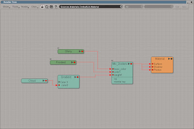
Start by open the scene xray.scn from this issues DVD. Select one of the vertebras and press [7] to open a Render Tree (they already have a constant shader applied). The first task is to make the objects transparent. For this you’ll need Gradient (Nodes > Mixers) to control the objects opacity, an Incidence (Nodes > Illumination) to control the mapping of the gradient and a Cloud texture (Nodes > Texture Generators) to brake up the uniformity. Open the gradient PPG and click the Black/White Preset button to clear the gradient and then add a new color marker approximately in the middle of the slider. Close the PPG and connect the Incidence to the input of the Gradient node and the Gradient to the scaletrans input of the Constant node.

From the Nodes > Texture Space Generators menu choose Projection. Connect the Projection node to the coord input of the 3D_cloud and the 3D_cloud to the color3 input of the Gradient node. Open the Projection PPG. Click the New button and choose Spatial. In the UV Remap section, change the Maximum on all three axis to 3 and close the PPG. Open the 3D_cloud PPG and set the Color 2 to black and lower the Contrast to 0.5.

From the Nodes > Image Processing menu, get an Invert node. Connect the Gradient to the input of the Invert node and the Invert node to the incandescence input of the Constant node. Open the Constant PPG and set the Color to a green color such as, R:0.4, G: 0.6, B: 0.4. Switch to the Transparency tab and set the transparency color to R:0.9, G: 0.9, B: 0.9. Switch to the Indirect Illumination tab and set the Incandescence Intensity to 0.3.

From the Nodes > Volume menu, get a Constant Density node, connect it the Volume input of the Material Node and open its PPG. Change the Transmit color to black and set the Unit Scale to 1:1.

The transparency can be modified with the Incidence node or the gradient node as well as the color sliders in the Constant shader. This ought to be enough for all your x-ray needs.

The project files used in this tutorial can be found at: http://www.redi-vivus.com/Caffeineabuse/XRay.zip

Quick tip
To see the effect of a specific node you can temporary connect it directly to the Surface input of the material node. Just don’t forget to reconnect the right node when you’re done.


Read the full post>>

Wednesday, May 20, 2009

Adding Ambient Occlusing as a lens effect

Adding AO globally
While you commonly would setup and render the ambient occlusion in a separate pass, it doesn’t mean it can’t be done in a single pass as well. By adding the AO to the camera rather than the individual materials, you can control the effect globally and you don’t have to change a single material. Open the scene cube.scn from this issues DVD. Press [8] to open an Explorer, select the Camera and press [7] to open a Render Tree.

Using a lens shader
Connecting the AO directly to the camera wouldn’t make much sense at all, but you’ll need a few other nodes as well to make it work. First you’ll need a lens shader. You’re not going to use any of its features, so any lens shader will do. From the Nodes > Illumination menu choose More. Go to the DSPresets\Shaders\Lens folder, select the Lens Effect and click Ok. Open the Lens Effect PPG and change the Mode to Bypass Effects.
The ambient occlusion
Add a Mix 2 Colors node (from the Nodes > Mixers menu) and an Ambient Occlusion (from the Nodes > Illumination menu). Connect the Lens_Effect to the base_color input on the Mix2color node and the AO node to the color1. Then connect Mix2color node to the Lens Shader input on the Camera node. Open the Mix2color PPG, set the Weight to pure white, R:1, G:1, B:1 and change the Mode to Hide/Reveal(Multiply).

The project files used in this tutorial can be found at: http://dl.dropbox.com/u/3834689/CaffeineAbuse/AmbientOcclusion.zip


Read the full post>>

Friday, May 15, 2009

Animating frost growing across the surface


Animating a gradient sweeping across the surface is a very quick and efficient way to create a transition from one material to another.

This is a very common question. Okay perhaps not the frosted effect, but the part about changing the textures or materials for an object over time. You obviously need a surface for the material so start a new scene and create a simple object. Or just open the scene frost.scn from this issues DVD. Select the frost object and from the Get > Material menu choose Phong and Press [7] to open a Render Tree. Get a Gradient node from the Nodes > Texture menu and a Mix 2 Colors node from the Nodes > Mixers menu. Connect the gradient node to the Weight input of the Mix_2colors node and the Mix_2colors node to the surface input of the Material node. Double click on the gradient node to open the PPG and switch to the Texture tab. Click the New button and from the menu choose Planar XY. Switch back to the RGBA Gradient tab and click the White/Black button in the Preset section to set the gradient to white and black. While this will create a nice gradual transition, it’s to uniform and unexciting. To break up the gradient you’ll need to add a new marker. Click somewhere in the middle of the gradient slider to add a third marker. With the new marker selected, click on the connection icon for the color and from the menu choose Cloud. Switch to the Texture tab, click the New button and choose Spatial. Switch back to the Cloud tab. Set the Clouds color to a light gray, such as R: 0.8, G: 0.8, B0.8 and the Sky to a slightly darker gray, R: 0.58, G: 0.58, B0.58. Switch to the Advanced tab and change the X,Y and Z maximum to 10.

From the Nodes > Illumination menu, add two Pong shaders and connect one to the base_color input of the Mix_2colors node and the other to the color1 input. Modify the Phong shaders to your liking and close the Render Tree. In a viewport, select the planar Texture_Support and scale it to about 0.4 on the Y-axis. Position it just below the frost object and press [K] to set a keyframe. Go to frame 50 and move the Texture_Support so it’s just above the object and set a new keyframe. Render the animation and you’re done.
Once the gradient is in place, you can replace the solid colors with textures to create complicated pattern.

The project files used in this tutorial can be found at: http://www.redi-vivus.com/Caffeineabuse/Frost.zip

Quick tip
You can create a completely different look for the transition just by replacing the cloud texture with any of the other textures nodes.


Read the full post>>

Thursday, May 14, 2009

Rendering XXL Sized images

While images for prominent 3d magazines may require a resolution of 300dpi, posters and billboards requires far less.
While the images for a typical brochure often are printed at a resolution of between 150 and 300 dots per inch (dpi) posters rarely exceeds 100dpi. Once you reach the size of billboards you’ll probably end up at a resolution less than 30dpi. With the above in mind you should have limit the need for extreme high resolution rendering, but there are situations when you do want the extra pixels. The central problem with large images is the amount of RAM needed. Not only do you need to cover the frame buffer/image itself which can easily grow to several hundred mega bytes (this is without considering the recourses need to actual compute the rendering) you also need to have this amount of free continuous memory.

The idea is to split the rendered image into smaller images and then stitch them back together in Photoshop or XSI Illusion (FX Tree) for that matter. This is done by changing the focal length of the camera and then shifting its optical center to the left, right, up and down. This won’t change the perspective in the image, just just which part and how much you see of it. To maintain the overall control of your shots, you’ll use one camera for the staging and four additional cameras for the render. Any changes made to the main camera will then automatically get propagated to the extra cameras by the use of expression, but with the added offset.

Open the scene SuperSize.scn from this issues CD. Press [8] to open an Explorer, expand the Cam_UpperLeft_Root node and click on the icon next to the Cam_UpperLeft to open its PPG. Switch to the Projection Plane tab and check the Enable checkbox. Right click on the animation icon (green dot) next to the Focal Length and choose Expression Editor. Enter Main_Camera.camera.projplanedist * 2 and click the Apply button. This will link the Focal Length to the main camera and double it (since you are to split the size of the rendered images in half). Open the Expression Editor for the Optical Center Shift X axis and enter Main_Camera.camera.projplanewidth * -0.5 This will offset the optical center by half the main cameras film aperture. Enter the expression Main_Camera.camera.projplaneheight * 0.5 for the Y Axis. Repeat the same procedure for the other three cameras. For the Cam_UpperRight use Main_Camera.camera.projplanewidth * 0.5 for the X shift, Cam_LowerLeft should use * -0.5 for both the X and Y shift (projplanewith and projplaneheight) and the Cam_LowerRight should use *-0.5 for the Y shift.

By using expressions the properties, and their added offset, is automatically propagated from the main camera to the extra cameras.

The project files used in this tutorial can be found at: http://www.redi-vivus.com/Caffeineabuse/XXL_Rendering.zip


In case the redi-vivus.com link doesn’t work, you can find a copy of the project files here: https://www.dropbox.com/s/qj37guhrl5k7qr3/XXL_Rendering.zip


Quick tipThe very same approach can successfully be used to create screen captures that is larger than your display resolution as well.


Read the full post>>

Coloring hair using procedural textures

Step 01
Creating the procedural
Select the pelt object and press [7] to open a Render Tree. Get a Fractal node (from the Nodes > Texture) and a Color Matte node (from the Nodes > Color Channels). Connect the Fractal node to the Input of the Color Matte node and the Color Matte node to the Ambient and Diffuse input of the Blinn node. Open the Fractal PPG. In the Texture tab, click the New button and choose Planar XZ. Switch to the Advanced tab and set the UV Remap Maximum to 5 for all three axis.


Step 02
Creating the texture


Open the Color Matte PPG. In the Component tab, change the Channel to Average RGB. Switch to the Component Range tab and check the Range Enabled checkbox. Set the Minimum delta to 0 (zero), the Minimum threshold to about 0.45 and the Maximum delta to 1. Change the Inside Value to a light brownish color and the Outside Value to a dark brown. Select the Color_Matte node and press [Ctrl] + [C] to copy the branch. Press [Ctrl] + [2] to switch to the Hair toolbar. Select all the polygons on the topside of the pelt and from the Hair > Create menu choose From Selection


Step 03
Transfer UV’s to the Hair
Select the Hair and from the Modify menu choose Transfer Map. Press [8] to open an Explorer. Expand the Pelt > Polygon Mesh > Cluster > Texture_Coordinates node and pick the Texture_Projection (Planar XZ). This will copy the UV information from the mesh to the hair operator. With the hair selected, press [7] to open a Render Tree and press [Ctrl] + [V] to paste the nodes from the Pelt material. Connect the Color_Matte to the DiffuseRoot input of the Hair_Render node.

The project files used in this tutorial can be found at: http://www.redi-vivus.com/Caffeineabuse/HairProceduralColor.zip


Read the full post>>

Animating a mechanic billboard in Softimage XSI

While the mechanical billboard is outdated at best, your virtual version is just about to start its glory days.

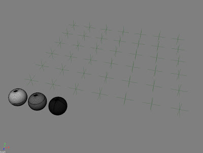
Start by opening the Billboard.scn scene from this issues CD. The scene contains a bunch of trilons or triangular prisms, 300 to be precise. Using a couple of thousands would obviously be more striking but for the sake of demonstration the number is keep low. While any of the prisms could be used to animate their rotation, it’s a good idea to separate the animation parameters from the actual billboard. Start by selecting the null object named Prisms_Rotation. Press [C] to activate the rotation tool and press [K] to set a keyframe at frame 1. Go to frame 16, rotate the Prisms_Rotation 120 degrees on the Y-axis and set a new keyframe. With the rotation still at 120, set another keyframe at frame 80. Press [0] (zero) to open the Animation Editor and select the function curve for the Y rotation (roty). From the Curves menu choose relative Cycle. To change the pace of your mechanic billboard, just move one of the 3 keyframes.

Press [2] to switch to the Animate toolbar. From the Create > Parameter menu choose New Custom Parameter Set. Enter Billboard as the name and click OK. Press [8] to open an Explorer, select the Billboard parameter set and press [Shift] + [P] to add a new custom parameter. Name the new Parameter Rotation_Delay. The parameter will be used to control the offset of the prisms. Changing the slider will automatically change the delay. The offset is evaluated in seconds; consequently you’re going to use very small values. Change the Maximum Value Range to 0.01 and click OK to close the PPG.

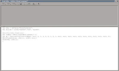
Open an Explorer and select the Prism_No1. Scroll down to Prism_No300 and shift select it to select all the objects in order from 1 to 300. Press [Alt] + [4] to open the Script Editor. Set your script language to Jscript (File > Preferences) and enter the text beneath.
Press the Run button in Script Editor to execute the script. Open the Bilboard PPG and playback the animation while changing the Time_Delay slider.

Using a simple loop in Jscript adds the expression with the delayed rotation in seconds rather than the frustrating hour required if done manually.

The project files used in this tutorial can be found at: http://www.redi-vivus.com/Caffeineabuse/Billboard.zip

Quick tip
The order in which the objects are selected also controls the extent of the offset, which in turn is set by Rotation_Delay slider. So, select the object in the order you want them to turn.


Read the full post>>