Your online Softimage Educational Resource

The blog has been online for more than 4 years and there’s still not a single post even remotely related to the delicious brew called coffee… Perhaps it will someday, but in the meantime you can read the articles about Softimage. Most of the material are tutorials and Q&As I’ve written for 3D World Magazine sometime between today and 2003. If you have any questions please don’t hesitate sending me an email.


Thanks to Letterbox Animation Studios for hosting all the scene files.

Make sure you visit their Redi-Vivus.com for 100s of hours of free XSI video tutorials.

Saturday, May 15, 2010

Rigging a piston engine


Image 01
For the reason that the relation between the crankshafts rotation and the pistons y position isn’t linear, a standard position constraint won’t cut it.


The concept of a reciprocating engine, commonly referred to as a piston engine, is in fact quite simple. Petrol gets injected into the cylinder and the piston pushes upwards to compress the petrol (fumes). The spark plug sets of a spark which ignites the fumes and causes it to explode. The force of the explosion sends the piston down through the cylinder. The piston is connected to the crankshaft via a connecting rod, which transforms the up and down movement into a rotation motion which in the end drive the wheels of the car. The piston is connected in pairs so when one piston is pushed down the other is pushed up which compresses the fumes, which is then ignited by the spark plug and so on.

The problem when recreating the setup in 3D is that the piston’s y position is not linear connected to the rotation of the crankshaft. The piston will move at different speed during a full rotation. Start by opening the scene Piston_Engine.scn from this issues CD. Select the piston and press [Ctrl] + [K] to open its local transform PPG. Right click on the animation icon (the green divot) for the Y Pos and choose Expression Editor… from the menu. Since you know the length of the of the connecting rod, 11 units, and the radius of the crankshaft, 1.5 units, getting the pistons Y position is merely a task of putting your high school trigonometry knowledge into practice.

Side a is calculated by multiplying c (the radius of the crankshaft) with cosines alpha. Before you can determine side d you have to calculate side b, which is done by multiplying c (the radius of the crankshaft) with sinus alpha. Once b is known you can use the Pythagorean theorem,

d2 + b2 = e2 => d= square root(e2-b2)

The full height (h) is sum of a + d

Enter the following expression in the editing pane, press the Apply button and then close the Expression Editor.

1.5 * cos(Crankshaft.kine.local.rotz ) + sqrt( pow( 11, 2 ) - pow( 1.5 * sin(Crankshaft.kine.local.rotz ), 2 ) )

Aligning the connection rod can easily be done in the same manner as in the previous equation. Or you can simply parent the connection rod under the piston and make it point to the crankshaft by using a constraint. Select the ConnectionRod_Rotation, click the Parent button in the Main Command Panel and select the Piston with the middle mouse button to make it the child of the Piston. With the ConnectionRod_Rotation still selected, click the Constrain menu and choose Direction. Pick the Crankshaft_Center when prompted. In the Direction Constraint PPG –Y button to align the Connection Rod.

The project files used in this tutorial can be found at:
http://www.redi-vivus.com/Caffeineabuse/Piston_Engine.zip
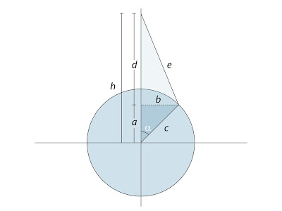
Image 02
A quick revisit to your high school trigonometry lessons is just want the doctor has ordered.


Quick tip
All the transforms are evaluated in local space, so to move or reorient the piston simply parent all the objects under a null (or any other dummy object) and you’re good to go.


Read the full post>>

Thursday, April 22, 2010

Single axis direction constraint


Image 01
While you can’t restrict the direction constraint to a single axis per se, using an extra object as a buffer will create the desired result.


As you’ve noticed there isn’t a one click solution to limit the direction constraint to a single axis. However there’s no need to despair as we’ve supplied you with two different methods to tackle the problem.

Open the scene Surveillance_Camera.scn from this issues DVD. The first method requires two null objects, one which can be moved in any direction and one that will be used for the actual direction constraint. Create a null object, name it Direction_Cns and move it somewhat in front of the surveillance camera. Create another null object, name it LookAt and move it in front of the camera as well. Press [Ctrl] + [K] to pen its Local Transforms PPG and click the Lock icon to pin it to the screen. Select the Direction_Cns object and press [Ctrl] + [K] to open its transform PPG as well. Click and drag the animation icon (the green divot) from the X Position in the LookAt PPG and drop it on the X Position animation icon in the Direction_Cns PPG. By dragging and dropping an animation icon from one parameter to another creates an equal expression, meaning the second parameter will match the exact same value as the first. Drag and drop the Z Position of the LookAt to the Z position of the Direction_Cns and close the PPG’s. Select the Camera_Orientation and from the Constrain menu choose Direction. Pick the Direction_Cns when prompted. Select and move the LookAt object to change the direction of the Surveillance_Camera. Save your scene under a new name.

The second method uses a somewhat different approach but has the same outcome. Open the Surveillance_Camera.scn again. Create a null object, name it Direction_Cns and position it straight above the camera. Create a second null, name it LookAt and position it in front of the camera. Select the Camera_Orientation object and from the Constrain menu choose Direction. When prompted, pick the Direction_Cns. Click the Y button in the Align Axis section of the Direction Cns PPG to correct the cameras orientation. Switch to the Up Vector tab. In the Optional Up Vector Control Object section, click the Pick New button and pick the LookAt object. Select Z as the Affected axis and close the PPG. While the direction is constrained to the Direction_Cns object, the added up vector gives you the final control of the cameras orientation. Select and move the LookAt object to change the direction of the Surveillance_Camera.

The project files used in this tutorial can be found at:
http://www.redi-vivus.com/Caffeineabuse/Direction_Constraint.zip

Image 02
The other way around it is to have the constraint pointing to a dummy object and then the up vector as the actual target for the direction.


Quick tip
In addition to naming convention it’s a good practice to use different colors and/or icons on your null objects. This way you can easily tell what objects does what by just looking at your scene.


Read the full post>>
Thursday, April 15, 2010

Assigning different textures to the same geometry-instances in ICE

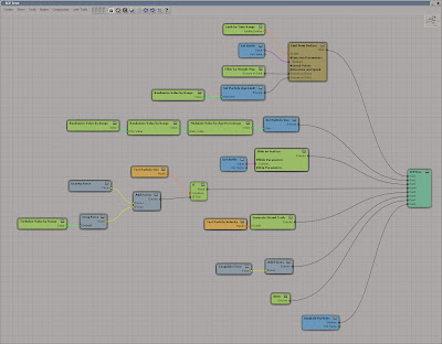
While you can’t assign different materials to the same geometry instances per se, you can use attributes from the pointclod to achieve the same result. Start by open the scene multiple_textures.scn from this issues CD. Select the PointCloud and press [Alt] + [9] to open an ICE Tree. With the pointcloud and the instanced geometry already in place, the only thing left to add is a random color. Get a Randomize Color by Gradient node and connect it to the Color input of the Emit from Surface node. Open the Randomize Color by Gradient PPG and change gradient to match the screenshot.

Select the can object and from the Get > Material menu choose Blinn to apply a material and then press [7] to open a Render Tree. While each particle has a random color assigned to it, the color information is not automatically passed on to the material. From the Attributes category get a Color node. Open its PPG and change the Attribute to Color.

From the Images Processing category get a RGBA Keyer and open its PPG. Set the both the Minimum and Maximum threshold color to R:0, G:1, B:0 (pure green). Set the Color if in rage to white (R:1 G:1 B:1), and the Color if outside range to black (R:0 G:0 B:0). This will create a mask where all the green particles will be output as white and everything else as black. Duplicate the RGBA Keyer node and change the Min and Max threshold color to pure blue (R:0, G:0, B:1).

In the Mixers category get a Mix 8 Colors node. Open its PPG and check the In Use checkbox for the Layer 2. Connect the Attribute Color node to the input of each of the RGBA keyer nodes. Connect the first RGBA keyer to the weight1 input of the Mix_8colors node and the second RGBA keyer to the weight2 input. Connect the Mix_8colors node to the diffuse and ambient input of the Blinn node. Add three image nodes, each with a separate texture, and connect the first to the base_color input of the Mix_8colors node, the second to the color1 input and the third image node to the color2 input. You’re now using three different textures on the same geometry-instances.

The project files used in this tutorial can be found at:
http://www.redi-vivus.com/Caffeineabuse/ICE_Textured_Instances.zip

Image 01
Using blocks of solid colors rather than the smooth gradient is a quick and efficient way to define random colors.

Image 02
The color information is then used in the Render Tree to assign a different texture to each of the colors defined in the gradient.


Quick tip
To change the balance between of the different colors (textures) simply change the markers position on the gradient.


Read the full post>>
Thursday, January 21, 2010

Water Condensation using ICE

On planet earth matter can traditionally exist in three physical states or forms; solid, liquid and gas. There are in fact a couple of more states such as plasma and liquid crystal, but let’s not get too technical. Condensation is essentially water changing it physical state of aggregation from gaseous into liquid (guess you’re glad we didn’t get in to the technical parts). One of the most common examples of this is the creation of clouds. As warm air rises to the atmosphere it cools and loses its ability to hold water vapor. The water molecules will then clump together to form cloud droplets, which then of course fall as rain (a phenomenon anyone who has visit England is far too familiar with).

This is the exact same thing that happens on a cold glass bottle on a warm summer day. Rather than forming small clouds around bottle the water vapor will form tiny droplets on any part of the surface that is colder than its surrounding air. Once the water droplets on the bottle reach a certain size or mass, gravity will grab hold of them forcing them towards the ground. As the water drop slides down the surface of the bottle it will attract any neighboring drops along its path, which creates a small water trail. The amount of water vapor the air can hold and the rate it condensate is determined by a number of factors. The characteristics of the water drops is then additionally affected by the material of the object and it’s surface.

Recreating the complete atmospheric process in real-time would pretty much be like watching paint dry (or the opposite). For your convenience we’ve speedup the course of action on the following pages, where you’ll create a complete and fully functional condensation compound using Softimage’s new interactive creative environment – ICE.

Note that covering a glass bottle with thousands of tiny water drops will obviously cost you once you hit the render button. The two most important attributes for creating a realistic glass or water material is their transparency and their reflectivity. As your entire scene is filled by nothing but the two, you will be required to crank up the reflection and refraction rays depth in the render options optimization tab. even tough the creation of these materials unfortunately falls outside the scope of this walkthrough; it shouldn’t be too difficult for you to create them on your own as ICE particles allows you to use any of the standard materials such as Blinn or Phong.


The project files used in this tutorial can be found at:
http://www.redi-vivus.com/Caffeineabuse/ICE_Water_Condensation.zip

STAGE ONE Preparing the bottle

Step 01
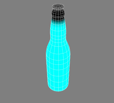
Start by open the scene Bottle.scn from this issue DVD. Staying true to reality means that any part of the bottle that is colder than the air surrounding it will be exposed to the tiny water drops. This would include the bottom and inside of the bottle as well. As these parts won’t be visible in your CG reproduction there’s no point wasting precious CPU resources to compute them, so you’re going to limit the effect to the outer surface of the bottle.

Step 02
To do so you’ll need to create a Weight Map to mask which area to emit particle and which will not. Select the Bottle and from the Get > Property menu choose Weight Map. Press [W] to activate the Pain Tool and with the left mouse button paint the outside of the bottle. Note that you can change the size of the brush by hold down the middle mouse button and drag to left or right and the right mouse button to erase painted area. When done, press [SPACE] to exit the paint mode.

Step 03
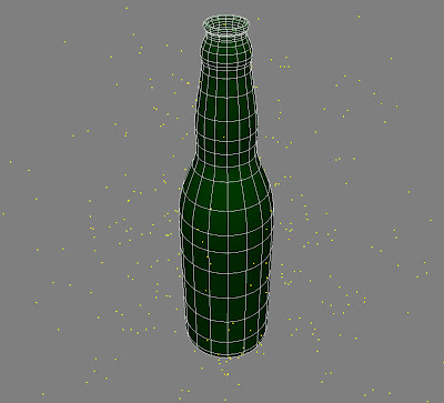
With the Weight Map in place it’s time to emit some particles. Press [4] to switch to the Simulate toolbar. With the Bottle selected, click ICE > Create > Emit Particle from Selection. This creates the PointCloud where all the magic will take place. If you play your animation you’ll se that particles are emitted from the entire bottle and fly off in to space. This obviously has to change, so press [Alt]+[9] to open an ICE Tree.
STAGE TWO Emitting the water drops
Step 04
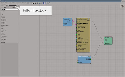
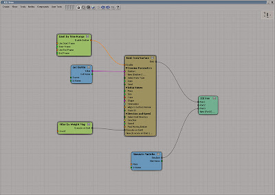
There are two tabs in the Preset Manager, Task and Tools. Under the Tools tab you’ll find all the low-level nodes of ICE and under Task you’ll find low-level nodes packaged together to perform specific tasks. A far quicker way to find the node you’re looking for than browsing trough the manager is by using the Filter text box. By entering the first character (or any character for that matter) in the text box it will automatically displays all the nodes that match your filter criteria.

Step 05
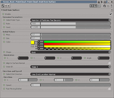
Double click on the Emit From Surface node to open its PPG. While it shouldn’t take more than a couple of minutes to get condensation on the bottle in real life, it just seems a little overambitious to reproduce the effect in real-time. So to speed up the process you’ll emit a good amount of particles (which in you case equals water drops,) for a few seconds and then leave it at that. Change the Rate to 500. You will alter the size of the particles later on so just leave it for now. Change the Shape to Blob and set the Speed to 0. Close the PPG

Step 06
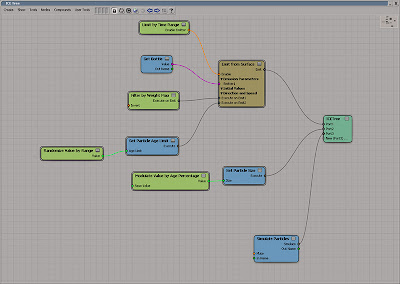
Get a Limit by Time Range node (by entering part of its name in the Filter textbox as described earlier). Open its PPG and set the Start Frame to 0 and the End Frame to 100. Close the PPG and connect the node to the Enable input of the Emit from Surface node. Get a Filter by Weight Map node and connect it to the Execute on Emit 1 input of Emit from Surface node. Now your particles will only be emitted from frame 0 to frame 100 and only from the area you’ve painted with the Weight Map.

Step 07
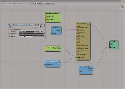
To add variety and dynamic to the water drops you are going to change their size based on how many percentage they’ve lived of their total life. By default the particles don’t have age awareness so this has to be added manually. Get a Set Particle Age Limit node and connect it to the New (Execute on Emit 1)… input of the Emit from Surface node. This will set the life of each particle in seconds.

Step 08
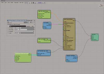
Your particles now have an age limit but they will all live for the exact same duration. Even though this alone should brake up much of the uniformity of the particles, it still lacks an organic touch. Get a Randomzie Value by Range node and plug it into the Age Limit input of the Set Particle Age Limit node. In the Randomize Value by Range PPG, change the Minimum Value to 1 and the Maximum to 200.

Step 09
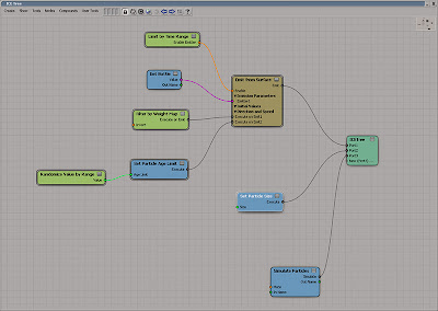
Let’s set the size of the particles. Get a Set Particle Size node and connect it to the Port2 of the ICE Tree node. The ICE tree is processed from left to the right and the terminator (the ICE Tree node) from top to bottom. The terminal node (the ICE Tree node) is then executed from top to bottom. So the Emit from Surface branch plugged in to Port1 will be executed before the Set Particle Size you’ve just plugged in to Port2 which is executed before Port3 and so on.
STAGE THREE Changing the particle size

Step 10
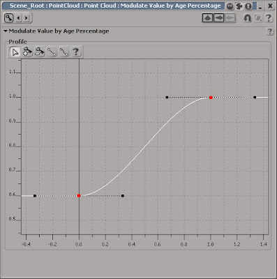
The Set Particle Size node won’t do much good alone since there is no data feed in to it. Get a Modulate Value by Age Percentage node and connect it to the Size input of the Set Particle Size node. Open the Modulate Value by Age Percentage PPG. The profile will determine how the particles size will change over time based on the Base Value. Were the left keyframe represents when the particle is born and the right keyframe when it reaches the end of its life.

Step 11
So if the left keyframe is set to 0.6 it means the particles will size will be 60% of the Base Value when it’s born. Select the left keyframe in the graph, right click and choose Key Properties from the menu. Set the value to 0.6. Click on the Next Key button. Set this Value to 1 and close the PPG. Using a single value as the Base Value means that all particles will have the same size at the beginning and end of their lives, even if their age limit will be completely different.

Step 12
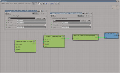
To get around this problem you’ll obviously need to use different Base Value for each particle. Get a Randomize Value by Range node and connect it to the Base Value of the Modulate Value by Age Percentage node. Open the Randomize PPG and set the Min Value to 0.1 and uncheck the Animated checkbox. Get a second Randomize Value by Range node and connect it to the Max Value of the first Randomize node. Open its PPG and set the Min to 0.1, the Max to 0.25 and uncheck the Animated checkbox.
STAGE FOUR Sticking to the bottle
Step 13
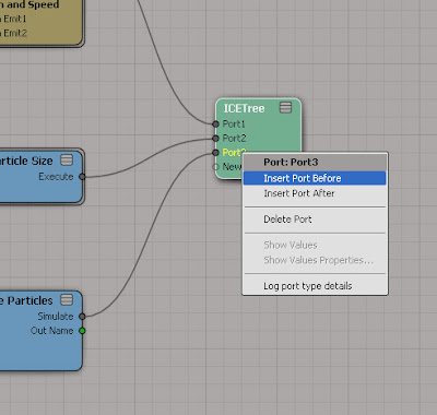
All the Ports of the ICE Tree node are currently occupied so you’ll need to add new Port. On the ICE Tree node, right-click on the Port3 input (currently occupied by the Simulate Particles node) and choose Insert Port Before from the menu. Add four more ports while you are at it, so you have five free ports in total. Get a Slide on Surface node and connect it to the Port3 of the ICE Tree node.

Step 14
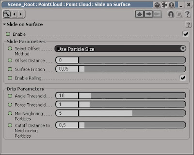
If you open the Slide on Surface compound PPG you’ll see a number of parameters to control at which angle the particles are allowed to drip of the surface, how many particles that needs to be together, how much force will be required etc. Since you’re basically just want to stick the water drops to the surface you don’t need to pay too much attention to these. Decrease the Angle Threshold to 10 or so and the Min Neighbouring Particles to 5. Close the PPG.

Step 15
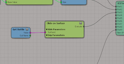
The particles don’t know which surface they are supposed to slide on, so you need provide this data as well. Press [8] to open an Explorer and drag and drop the Bottle object from the Explorer in to the ICE Tree workspace. Connect the Output value of the Get Bottle node to the Surface 1 Input of the Slide on Surface node.
STAGE FOUR Adding Gravity

Step 16
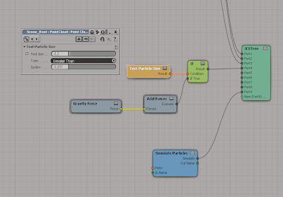
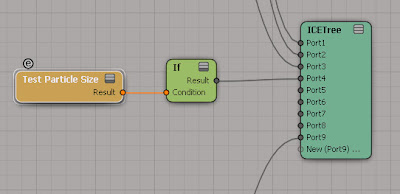
If you simply add a gravity force to the ICE Tree, all the particles would be affected and run down the bottle straight away. While you do want a gravity force, you only want the particles that are above a certain size to be affected. Get an If node and a Test Particle Size node. Connect the Result output of the If node to the Port4 input of the ICE Tree node. Connect the Result output of the Test Particle Size to the Condition input of the If node.

Step 17
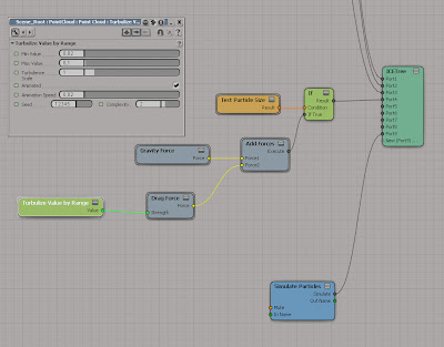
Open the Test Particle Size PPG and set the Test Size parameter to 0.2. If the particle size greater than 0.2 the Condition is true, and the If True port will be executed. If the size is less that 0.2 the If False is executed which in your scenario means that nothing will happen. Get an Add Forces node and connect it to the If True input of the If node. Get a Gravity Force and connect it to the Force1 input of the Add Forces node.

Step 18
Get a Drag Force and connect it to the New (Force1)… input of the Add Forces node. This will create a flow resistance to the particle and balance the force of the gravity. To further enhance the variation of the particles motion you’ll turbulize the strength of the Drag Force. Get a Turbulize Value by Range and plug it into the Strength input of the Drag Force. Open its PPG and set the Min Value to 0.02 and the Max Value to 0.1. Close the PPG.

STAGE SIX Creating a water trail

Step 19
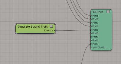
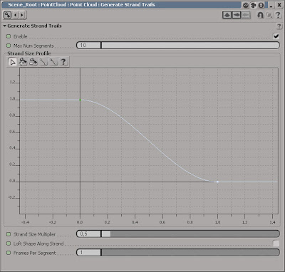
As the water drops run along the surface of the bottle they will leave a fine trail of water. Get a Generate Strand Trails node and plug it into Port5 of the ICETree node. Open the Generate Strand Trails PPG. Set the Max num Segments to 10. This parameter controls the length of the trail, the higher the value the longer the water trail.

Step 20
The Strand Size Profile determines the size of the trail, which in this scenario means overall shape. Select the right keyframe, right-click on it and choose Key Properties from the Menu. Set the Value to 0. This will fadeout the water at the end of the trail, giving it a more realistic shape. Set the Strand Size Multiplier to 0.5 to tone down the overall trail.

Step 21
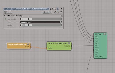
Just as with the gravity, you don’t want to create trails on all the particles in the simulation but limit the effect to the drops that are actually moving down along the bottle. Rather than testing the particle size you’ll test the particles velocity. The particle will only leave a trail if its velocity exceeds a certain number. Get a Test Particle Velocity and connect it to the Enable input of the Generate Strand Trails node. Open the Test Particle Velocity PPG and set the Test Velocity to 1.
STAGE SIX Coagulate force

Step 22
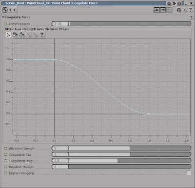
So you have gravity, drag, water trails and the actual surface of the bottle all taken into account, but the particles still don’t have any affect on each other. The coagulate force enables you to attract particles together, creating small lumps of particles (which of course creates a slightly larger water drop) based on their distance to each other. The force can have a drastic effect on all your particles so the trick is to use small subtle values.

Step 23
Get an Add forces node and connect it to the Port6 input of the ICETree node. Get a Coagulate Force node and connect it to the Force1 input of the Add Force node. Open the Coagulate Force PPG. The Cutoff Distance determines the maximum distance allowed between two particles for the force to have an effect. Set the Cutoff Distance to 0.15. Increase the Coagulation Drag to 0.4 to slow down the particles as they get closer and set the Repellent Strength to 0.

Step 24
The very last node to add in this walkthrough is to control the amount of blending between the water drops. Get a Blobs node and connect it to thePort7 input of the ICETree node and you’re ICETree is completed. Before you apply the water and glass material to your scene elements it’s wise to do test rendering and fine-tuning of the particles using a standard Blinn shader. The number, size and characteristics of the water drops all relate to the temperature and humidity of the air as well as the surface of the bottle but perhaps more importantly, your personal taste. All the above values should be used merely as a guide in your quest for the perfect condensation.


Read the full post>>
Wednesday, December 23, 2009

Problem Downloading project files

There seems to be a slight problem downloading the project files for the tutorials. Please let me know if you experience this and I’ll send you the files via email…


Read the full post>>
Merry Christmas and Happy New Year!

Just wanted to wish you all a merry Christmas and a happy New Year! While I haven’t much time lately to add more articles there are some goodies waiting to be published, so stay tuned…


Read the full post>>
Thursday, December 3, 2009

Animating a cable using Softimage cloth


The project files used in this tutorial can be found at:
http://www.redi-vivus.com/Caffeineabuse/Cable_Using_SoftimageCloth.zip


Softimage Cloth
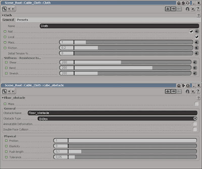
Start by open the scene cabel.scn from this issues CD. Select the Cable_Cloth object and press [T] to set the selection filter to points and select the two vertices at the right end of the object. From the Edit menu choose Create Cluster with Center. Press [4] to switch to the Simulate Toolbar. Select the Cable_Cloth object and from the Create > Cloth menu choose From Selection. Different types of cables obviously has different characteristics. Use the values in the above screenshot as a starting point and experiment on your own.

Local Cloth Cluster
Now, select the two vertices again and from the Create > Cloth menu choose Local Cloth Cluster. Make sure you check the Nail checkbox in the Cloth PPG. Select the object again and from the Get > Force menu choose Gravity. Select the Cable_Cloth again and from the Modify > Environment menu choose Set Obstacle. When prompted, pick the Floor object. Right click to end the picking session. In the Floor_obstacle PPG increase the friction to 0.8 or so to stop the cable from sliding all over the place. Set the Push length to 0.1 to compensate for the cable’s thickness.

Extract from edge
Select all the edge along one side of the cloth object. Press [1] to switch back to the Model toolbar and from the Create > Curve menu choose Extract from Edges. This creates a separate curve object from the selected edges and because it’s a live operator the cloth simulation will automatically be propagated as well. Name the curve Cable_Path. From the Primitive > Curve get a Circle and set the Radius to 0.05. From the Create > Poly.Mesh menu choose Extrusion Along Curve and pick the Cable_Path curve when prompted. Animate the Null object and your cable will follow perfectly.


Read the full post>>