Your online Softimage Educational Resource

The blog has been online for more than 4 years and there’s still not a single post even remotely related to the delicious brew called coffee… Perhaps it will someday, but in the meantime you can read the articles about Softimage. Most of the material are tutorials and Q&As I’ve written for 3D World Magazine sometime between today and 2003. If you have any questions please don’t hesitate sending me an email.


Thanks to Letterbox Animation Studios for hosting all the scene files.

Make sure you visit their Redi-Vivus.com for 100s of hours of free XSI video tutorials.

Tuesday, October 28, 2008

Particle Caching in Softimage XSI


Step 01
Caching the particles
Start a new scene and press [4] to switch to the Simulate Toolbar. From the Create > Particles > From Primitive menu choose From Grid. Under the Simulation tab in the Particles operator PPG change the Execution State > Mode to Standard Caching. Switch to the Output tab and set a unique name for the particle files. Go to the last frame in your animation to make sure you’ve cached the entire simulation. Select the particle cloud and press [H] to hide it.


Step 02
The Particle player
While the cached PTP files stores all the information for the particles position and orientation and so on they doesn’t store any information about the particle type (which includes how they’ll appear when rendered). To bypass this “little” problem you’ll need to load the cached files in the same scene as your original cloud. This way, the particle player will use the cached files from the hard drive but the ptype from the original cloud.


Step 03
Loading the cached files
From the Create > Particles menu choose From File. Browse to the simulation folder in your current project and select the cached particle files and click Ok. In the Particle Player PPG, set the Duration to match your simulation. Now, if you want to make any changes to your particles just unhide the cloud, make your changes and make sure you run the entire simulation. Hide the cloud again and the Particle Player is automatically updated.


Read the full post>>

Saturday, October 25, 2008

Animating Growing Vine


Wile the animation can easily come of as rather complicated it isn’t all that difficult to setup in XSI.

Start by creating a cone from the Get > Primitive > Polygon Mesh menu. Set the Length to 30 and the Base to 0.2. Increase the U Subdivisions to 12 or so and the V to 50. Name it Liana. Click the Center button in the Select menu and in the front viewport, move the object’s center all the way down to the bottom of the liana. This will create the effect of the liana growing from its base rather the center of the object. Since lianas usually don’t grow in perfectly straight lines, you’ll need to give it a bit more organic shape. From the Create > Curve menu choose Draw Cubic by CVs and draw a curve in the top viewport. Make sure you scatter the points a bit on all axes to give the liana a nice three dimensional flow. Now, select the liana object and from the Modify > Deform menu choose by Curve. Pick the curve when prompted. In the Curve Deform PPG start by switching to the Constraint tab and check the Constrain to Deformer checkbox. Switch back to the Curve Deform tab and change the Translation Along Curve so the liana lines up with the curve. Set the Scaling Along Curve to 0 and set a keyframe. Set a keyframe for the Roll parameter as well. Go to frame 100, set the Scaling Along Curve back to 1, the Roll to -145 set another keyframe on both parameters. From the Get > Primitive > Curve menu choose spiral. Set the Height to 20, the End Angle to 3600, the Start Radius to 0.25, the End Radius to 0.15 and finally the Subdivisions to 100. With the spiral selected, from the Modify > Deform menu choose by Curve and pick the same curve that is used to deform the liana. Change the Axis to Z, check the Constrain to Deformer checkbox and change the Translation Along Curve till they line up. Create another cone and make it longer but thinner than the first liana. Apply a Deform by Curve operator and pick the spiral curve. Animate in the same manner as the first liana.
The project files used in this tutorial can be found at:
http://www.Redi-Vivus.com/Caffeineabuse/Animating_Growing_Vine.zip
Adding a twist deformer, or any other deformer for that matter, to the liana before deforming it along the curve will add to the overall appearance of the animation.
Quick tip
To make the liana really stick to the surface of another object you can add a Shrink Wrap deformer to the curve. Change the projection to Closest Surface and lower the Amplitude to keep the objects from intersecting.


Read the full post>>

Symmetric modeling


Step 01
Clone your object
While there are a number of ways to (at least partly) do so, none of them are completely without flaws. However, don’t let this stop you from setting up one of your own. Select your (half) object and from the Edit > Duplicate/Instantiate menu chose Clone Single. Any changes made to your original object will automatically propagate to the clone but changes made to the clone object will not affect the original.

Step 02
Symmetrize the polygons
From the Modify > Poly.Mesh menu choose Symmetrize Polygons. This will mirror all the polygons, creating the missing half of the model. Press [Ctrl]+[4] to switch to the Palette toolbar and click the W button in the Display Types section. In the viewport or an explorer, pick your original object and then right click to end the picking session. This will set the objects display type to wireframe

Step 03
Easier interaction
In the Viewports menu bar > Display Types menu, uncheck the Override Object Properties. Select the clone. In the Select panel, click the Selection button and click on the Visibility node in the pop-up explorer. In the Visibility PPG uncheck the Selectability checkbox. This will keep you from unintentionally selecting it. Finally, open the Visibility PPG for the original object and uncheck the Render Visibility to prevent it from being rendered.


Read the full post>>

Modeling a bottle cap


The bottle cap is easily created by drawing a number of curves, each representing a different cross-section.
Regardless of the task at hand, the importance of good reference material can never be stressed enough. So, the only responsible thing to do in this scenario is to visit the closest pub for the ungrateful and cruel duty of gathering reference material.

Once you’re done (and hopefully sobered up a bit) start XSI and from the Get > Primitive > Curves menu choose Circle. You will need 4 points to create the shape of each tooth and you will need 21 teeth, so set the Radius to 1.25 and the Subdivisions to 84. Rotate it 90 degrees along the X-axis, press [Ctrl]+[D] to duplicate the circle and move it down 0.15 along the Y-axis. Now press [T] to set the selection filter to points and select every 4th point along the entire circle. Once selected, scale them about 1.06 along the local x and y axis’s so they’re just protruding the edges of the first circle. Duplicate the new circle and move it down another 0.1 units along the Y-axis. Press [T] to select the points again and scale them about 1.06 again. Click the Select button in the Main command panel and choose Invert Using Filter. Scale the new selection of points to about 0.98. Duplicate the circle again and move it down about 0.15 units along the Y-axis. Press [T] to select the points again and scale them about 1.01. Click the Select button and choose Invert Using Filter and scale the new selection 1.03. These are all very small values, but then again the teeth on the bottle cap aren’t big either so even the smallest adjustment will make a big difference. To create the top of the cap, select the first circle (the one which is perfectly round). Duplicate the circle, scale it down to about 0.93 and move it upwards 0.35 along the Y-axis. Create another duplicate, scale it down to 0.65 and move it upwards another 0.3 units. Create the the last duplicate and scale it to 0 (zero) and move it upwards another 0.05 units.

From the Create > Poly.Mesh menu choose Loft. Now pick the curve at the very bottom, then the one just above, etc till all the curves are selected. Right click to end the picking session. In the Loft PPG change the U and V span to 4 and you’re done.
The project files used in this tutorial can be found at:
http://www.Redi-Vivus.com/Caffeineabuse/Modeling_a_bottle_cap.zip
Since the loft operator is ‘live’, any changes made to the curves will automatically update the geometry as well.
Quick tip
By adding a bend deformer with low vales you can avoid the otherwise unnatural perfect look. Or you can use high values to actually fold the cap.


Read the full post>>

Thursday, October 9, 2008

Offset in Time


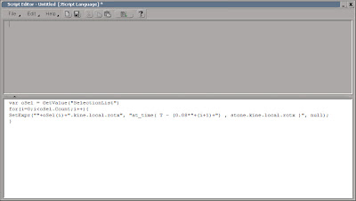
To change the offset of the stones, simply change the 0.08 value in the script editor and run the script again.
If you don’t have a deck of dominoes of your own, start by opening the dominoes.scn scene from this issues CD. Select the stone object, from the Main Command Panel > Constrain menu chose Curve (Path) and chose the dominoes_path curve when prompted. In the Path Constraint PPG, switch to the Tangency tab. Check the Active checkbox and click the –Z button to align the stone. Leave the PPG open, because you’ll return to it in just a few seconds. With the stone still selected, press [Shift]+[Ctrl]+[D] to open the Duplicate Multiple PPG. Enter 30 as the number of Copies and press OK. Press [8] to open an Explorer. Select the stone object, hold down [Shift] and select the stone30. This is important as the order in which the objects get selected will determine in what order they’ll get distributed. Return to the Path Constraint PPG and enter L(100) in the Path %age. This will distribute all the selected stones evenly along the curve. Once that is done you no longer need the path constraint, so with all the stones still selected chose Constrain > Remove All Constraints.

While you’re more than welcome to animate each stone falling onto the next and so on by hand, once you reach your second or third stone you’ll probably realize it just isn’t a viable solution. A more convenient approach is to animate a single stone and then pass on its animation to the others, each with the time slightly offset. Select the stone and set a keyframe for the rotation. Go to frame 4, rotate the stone -37 degrees on the X-axis (so the stone just touches the next stone) and set a new keyframe. Go to frame 15, rotate the stone to -82 degrees and set another keyframe. Next, press [0] (zero) to open an Animation Editor and change the slope handles on the fcurve to match the screenshot. Open an Explorer and select stone1 to stone30 and open the Script Editor. Enter the following lines and press the Run button. This will loop trough your selection and creates an expression which referencing the animation on the x-axis and applies an additional offset of 0.08 seconds for each stone.
The project files used in this tutorial can be found at:
http://www.Redi-Vivus.com/Caffeineabuse/Offset_in_Time.zip


Any changes made to the first stone’s animation will automatically change the animation of all the others, as their controlled trough an expression.

Quick tip
This approach is by no means limited to dominoes stones. The same expression can be used in numerous situations where you want to use the same animation on many objects, but offset them in time.


Read the full post>>