 STEP 01 Trigonometry
While the solution could easily grow into a profound setup among the rules of Trigonometry, doing the initial calculations by hand will save us some time (and hassle). As there’s a fixed relation between the rotation of the different gearwheels and their diameter, it’s merely a matter of linking each wheel to a master wheel, add compensation for the differences in circumference and use the master wheel to control the rotation and speed for all of hem.
 STEP 02 - Setting the expression
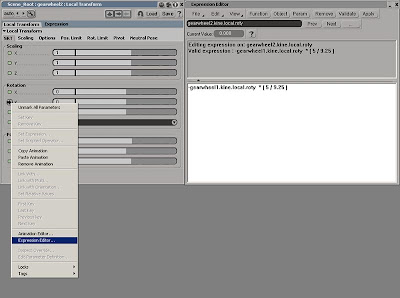
 Open gearwheel.scn and select the gearwheel2 and press [CTRL + K] to open its Transform Property Editor. Under the Rotation section, right click on the animation icon (green dot) next the Y-axis and click Expression Editor from the menu. In the Editing Pane (the white area) enter ‘-gearwheel1.kine.local.roty * ( 5 / 9.25 )’. Click the Validate button to ensure you’ve typed the expression correctly before clicking the Apply button.
 STEP 03 Gear up
The minus sign in the above expression will make the gearwheel turn in the opposite direction of the master wheel, whereas the numbers in the parenthesis compensates their different sizes by dividing the diameter of the gearwheel1 (master wheel) with the diameter of the current gearwheel. Select the master wheel and rotate it along the Y-axis to check the functionality. Continue by adding expressions to the other gears in the same manner.
The project files used in this tutorial can be found at:
http://www.Redi-Vivus.com/Caffeineabuse/Rotating_Gearwheels.zip
http://www.Redi-Vivus.com/Caffeineabuse/Rotating_Gearwheels.zip
Read the full post>>


